Friday, 16 May 2014

Engine Installation and Setup

Now that the engine is back from the dyno and the oil (scavenge) problems are sorted, it's been time to do final preparation on the engine bay and sort out all the support systems.
You know - oil, fuel, electrical, exhaust, coolant, etc, etc.

First thing to do was finish the engine bay paint and i did this with POR-15 chassis  paint (rust protector) in satin black.

On top of this I installed some heat reflector/shielding (from Thermo-Tec) rated to 2000 degrees F.
This self-adhesive shielding sticks really well to the engine bay paint so i'm hoping it does the primary job of keeping heat out of the cabin.
I have some tricky areas where the headers come close to the steering joints, the starter, the power steering hoses, and also the dry-sump scavenge lines - so i need to protect all of these items sufficiently to avoid damage from exposed heat soak.

The photo below shows the firewall and transmission tunnel after applying the reflective shielding.


The headers themselves are covered in insulating "wrap", but i also have a starter-motor heat-shield mat (held in place by stainless ties), as well as "Thermo Sleeves" to cover the battery cable enters the engine bay and bolts up to the starter motor, and also to cover the power steering and rear oil scavenge line.
This photo shows the engine in its final home. A huge milestone for me (plus proof a 429/460 with A460 heads will indeed fit in an early 1965 or 66 Mustang).

 
The following photo shows how i've positioned the engine as far back as i dare.
I can still get the rocker covers off, but i also made this easier on myself by welding a 7/16th UNF nut onto one of the engine mounts. This then lets me thread in a 7/16th bolt that i simply "screw in" as if tightening the bolt - and this slowly slides the engine forward on its mounts to give me plenty of work room.


This little trick also allows me to fine-tune the final "fore-aft" positioning of the engine as well.

The photo below is included only to show that i am hooking up all the engine ancillaries (for the all-important first test start).
To get to this point i've had to complete all the break & clutch lines, as well as fill with fluid and bleed. Let me just say it took quite some time to bleed everything because of the angles of the clutch slave cylinder (under the dash and in a vertical rather than usual horizontal position), and the location/orientation of the brake biasing valve. Both these units needed to be temporarily "re-oriented" to get the residual air out of their respective systems!
Apart from the hydraulics, i needed the drive-shaft installed, the 3 fuel pumps, regulator, return-line, fuel-rails etc all pressure-tested, and also a temporary accelerator pedal built.... plus more......

After all looked ok, a nervous author hit the start button. I have some video of the first moments that the car moved under its own power, but the dam file is too big to load. Regardless, I drove it all of 10 meters to get it to the back corner of the yard and out of the way for a teenage party coming up. This was my "compelling event" to get it rolling.
The 2 photos below are simply included as i liked the look of them.


The rear valence and bumper are removed only because i was testing for leaks in the custom stainless tank (no issue there thankfully), and you can also see that the engine wiring has been draped up over the dash. The Autronic EFI control module just sat on the passenger seat.


Lastly, here is a picture from the front showing how temporarily some systems have been implemented. The external dry sump tank is the good old trusty plastic bucket held in position with hay-band. The coils are taped onto blocks of 2x4 that sit on the rockers, and a keen eye will see the oil pressure guage is the only "important" guage used. No need for a radiator obviously when it's being driven only a few meters.....


I have since reversed it back into the garage and have it up on stands again. The next set of jobs is to do final brake bleeding, fabricate a custom exhaust (hopefully a full 3" system will fit between the coil-overs and up over the diff'), fabricate a final dry-sump reservior, install the front sway bar, install the final coolant lines and radiator, install the engine "front dress" for alternator and power-steering pump mounts - and maybe even run wiring to the front for lights and blinkers.

Actually - that is a heap of work when listed as such. So future posts will cover them.....

Monday, 17 March 2014

Engine Dyno Session

I'll give you the pictures first (some are blurred - sorry, these are the only ones I have as the day was so busy), then a summary..............

The engine (finally) at the Dyno shop and the drive hub mounted to the crank.


Above is the actual Dyno unit and the engine all hooked up. I started to get very vervous that this point...... And below is just one of many interim results showing it got 525Hp and 596Ft/Lbs of torque when being mapped at 70% throttle. The two "gauge" displays at lower left keep the last set of results and the photo below that shows the mapping being done at the various load and rev' points.
We had just run it from 1000 to 6000RPM while holding 70% load (throttle position in my case).
This is how the Autronic EFI unit is tuned and you need only 1 or 2 seconds at each tuning site.
So once everything is setup, it all happens pretty fast. Trouble was - it took a long time to setup.


And finally - the actual dyno sheet. 604Hp and a nice flat torque curve that sits in the mid 500's.
The dyno sheet doesn't lie - and this is my baseline now. However, this is just part of the story and I believe there is plenty of room for improvement.


Why do I say that? Because this run was the only one I could do as I ran out of time and money.
There was a lot of sorting required to get to the actual final "run".
Major problems were.....
  • Harmonics caused my crank sensor to oscillate and hit the trigger wheel. Had to fabricate the whole thing again on the day.
  • My initial spark plugs (suggested to me) were the wrong heat range. Found replacements (thanks John) and it was a very (incredibly) different motor.
  • Worst issue was some of my glyptal internal engine paint flaked off and blocked the finer stainless mesh filters I had located inside the dry-sump itself. My fault - 100% no doubt.
  • This meant oil was pumping in ok (from a large reservoir) , but not escaping at all for the dyno run.
So I only got the one run done and ran out of time to put some ignition advance into it. The above figures came at 25 degree max advance - no danger of pinging at that rate.
Just as importantly, the above figure came with at least 12 litres of oil sitting inside the dry-sump and crank case. I took 12 litres out when I got it home, but heaps had already leaked out. That engine probably thought it was trying to sprint in thigh-deep water......
 
I've sorted out the "paint flake" issue, and I'm hoping that the 596 Ft/Lbs I saw earlier (when tuning) was in a large part lowered on the dyno run because of the oil issue.
 
Also, see how the HP figure flat-lines at about 5750RPM?
Again, I'm hoping that is because of the retarded timing I went in with - because I know the induction, fuel and spark are good to go to about 8000RPM. Not that this engine will ever see those kinds of rev's, 6500 will be my conservative limit I'd say.
 
But - the EFI is now mapped and I can install it in the car and tweak it from there. I'm happy to say I have a reasonable base to work from now (solid engine) and there should be a big "upside" with some more tuning. Putting in some more ignition advance should really make a difference (make it jump) I'd say.
Anyway, now a couple of recent photos. First of the new filter screens I've built - to stop anything dropping down those (large) ports. I'll have a proper cold air box with normal filters in the final configuration. But these make me feel a lot safer for now.


And here is the latest photo showing that I'm just about to slide the Tremec into place.
Had a false start with the original hydraulic slave cylinder (too short), but the new 1400 series McLeod unit has fixed that.


Thinking ahead, the next post should be of the engine going in. Or maybe the interior - as I've been working on that in parallel to the above engine "project".


Monday, 17 February 2014

Engine Startup

Finally - I have started the motor for the first time, in preparation for the dyno.

Seeing dyno time is typically charged as an initial minimum set fee, then also for the amount of time you spend there, i want to make sure i don't waste time chasing electrical or leakage issues. Therefore - I want to get the engine initially idling reasonably well, the oil pressure where it should be and the coolant system operating as it should.
The 100% temporary stand you see below is actually a lot studier than it looks. It's made from 3mm wall-thickness box tube and all joins are fully welded. I have included the poly-urethane engine mounts in the construction as well just to give it a bit of movement


In case anyone is wondering, I have both a hose and a fire-extinguisher close by in case a disaster happened. But the nice thing about EFI is that you can pressure test the whole fuel system first - as the EFI pumps prime things up without having to turn to engine over. Secondly, you can crank the engine to make sure you are getting spark too.

That "dry sump" reservoir you see at lower left is a nice piece of Tupperware that sits in a box so it doesn't topple over. I have various sieves and magnets in it to catch any metal fragments. I caught a few too (nothing un-toward), as well as a few flakes of Glyptal paint. It just goes to show that no matter how clean you go (and i was paranoid about it) some bits just "appear" when a motor first fires.
Another benefit of the dry sump is that you can easily slip the high-torque-drive (HTD) belt off and spin the pump over with an electric drill. I did this a few times of course before the first start with the rocker cover off to watch the oil come up through the pushrods. This pump seems to sit at 70lbs pressure from about 1200 RPM onwards. It sits at 40lbs at an 800rpm idle.

I would have loved to upload the video of the first time the engine fired with coils on the right plugs and zero spark advance (to make sure the crank sensor was in the correct place)...... But the file is just too big and let's just say the video function on my camera does not do the sound justice. This thing is seriously loud.

I expected that of course having those big headers, but the deep sound it has from 520 cubic inches vibrates the whole house. Add to that a few initial timing issues where i had the wrong coil on the wrong plug (my fault) which produced some stunning back-fires (equivalent to a shotgun). The result of all this fiddling and head-scratching of course is that my neighbours really love me just now.......(not!).
Since that first startup, I have put some spark timing into it and it runs very crisply for the few seconds I have it going (very short bursts for now as i have no coolant in it). My next task is to finish the coolant system by plumbing in those remote electric water pumps and controller. Once that's done it's off to the dyno (finally).

Monday, 20 May 2013

Engine Assembly & Header Build

I've been waiting a long time to get to this point.
I finally collected sufficient engine components to justify actual engine assembly. I have run into one last (self-inflicted) hurdle though that I explain at the end of this post, but for now, here is what's been happening for the last few months.
First off, check out the very nice induction setup (below) that was the result of a heap of preparation work by myself and then some great help from Robbie out at Flexicut Engineering. I thought up the original design and had it created in a CAD/CAM program. Robbie then adjusted it to make it more practical to cut on the CNC machines to save a heap of time (= money).
I can't thank you enough Robbie for the "extra mile" you went to in helping out with the coolant exits, the engine valley plate, the throttle linkages, throttle rail mounts, various spacers, etc.
The picture below shows how nice it finished up.


I was originally going to anodize parts of it - but it looks good as is (my opinion). So it will remain as a natural finish (natural for T6 alloy).
In case anyone thinks the above was straight-forward or easy to do, there are a heap of design tweaks implemented to get it all to work (fits like a glove actually). And then there are some mod's I would add in hindsight as well - now that it is all bolted up. But regardless, the results are fantastic.
As you can see, i've gone for short & straight runners. Ideally i would include some wedges to position the trumpets more upright (and minimise the potential for cylinders to rob air from each other), but i think this will work ok. The motor will have plenty of natural torque at low rev's to compensate for the short runners at low RPM's.

Now for the engine build.
Firstly, here is the crank and cam being degreed-in, so i can fly-cut another set of pistons.... I sold the last set to a guy that needed them sooner than me. You can see the yellow plasticine being applied again for this task (to measure valve to piston clearance).


And here is the result. I took another 100 thou off the pistons to ensure plenty of clearance for the intake valves. The exhausts had heaps of room by default. What this process doesn't show however - is the time spent making another jig so each piston could be cut exactly the same, as well as the effort that goes into making sure each piston weighs the same to 1/10th of a gram.......


And below you can see the conrods having been prepared and numbered.


This photo just shows my routine for gapping piston rings. I make sure I don't mix them up by leaving them in the bore. And then I..........


....place them back in the box in the position the pistons came out of so I can minimize any chance of putting them in the wrong bore.


Here I finally have the short-block complete.
Things to note are:
  • I am running a Canton main-girdle as a stroker engine needs all the bottom-end help it can get. This is a cheap investment, but in this case it needed mod's to give it the minimum 60 thou' clearance (in a few spots).
  • Degree-ing the cam showed it was 2 degrees advanced compared to advertised spec's. So I've retarded it by this amount to install it "straight up".
  • The mechanical roller-cam has +.700" lift with "reasonable" duration by the way.This should work well with the induction setup i have i believe (but the dyno will prove this one way or the other).


And below you can see I've bolted the heads and valley plate down. I had to build my own "crows foot" socket to allow the torque wrench to reach the nuts (on the head studs) running down the middle of the heads. The big valve springs simply would not allow a standard 11/32" socket to be used.
My "crows foot" socket was made by cutting as standard socket in half so i had the half-inch drive end separated from the socket end.
I then welded them back together, but "offset" by welding a short length of "chopped up old spanner" between them.
I made the center-to-center distance of my new crows-foot exactly 1/10th the length of my torque wrench. This made it easier to calculate the revised torque wrench settings to use as i just needed to take 10% off any recommended settings (as my new torque wrench + crows foot length was 10% longer overall).


Because of the high-lift roller cam and associated heavy-duty valve springs, I went for a stud-girdle as well. I think this is even more important with alloy heads as they do move more than cast iron units. Again, this is just my opinion.


And below you can see the valve covers have been put on and the ports all masked up for yet another trial fit. But this time in order to fabricate the headers. This picture does tell a thousand words (for anyone contemplating this engine/chassis combo.........
You can see that the RRS shock-tower notching kit gives me heaps of room for the first part of the pipes as they exit the heads. This is good news - but I ended up needing absolutely every inch of space I had seeing my header "weld up" kit has 2-1/4" primary pipes combining into a 4" collector.


The photo below shows that there is plenty of room for the pipes as they exit the heads. A keen eye will even see the 4" collector dummied into position all the way at the lower rear. That is fine, but as my car is converted to right-hand-drive - I then had to contend with both the starter motor and the power rack & pinion linkages on the same side of the car (the side shown below).
I think i did 1000 situps in 2 and a half days building these bloody pipes. I knew it was going to be painful but when you are doing this on your own, you seem to endlessly repeat the following tasks: hand cut and fit some pipe, then tack-weld, then remove he header and fully weld, then re-install, then hand cut and fix the next section...... You do this over and over and over.....And you get under the vehicle then get up again for each step


The result was worth it though. Below are the custom pipes almost done.


Once the headers were done and the oxygen sensor ports welded in, I could start to do final assembly. The photo below shows the engine 90% complete and on a temporary engine stand. I'm going to use this stand to initially fire the motor up before going to the dyno - as I want to be sure it starts and runs first.
Dyno time isn't cheap, so getting it started and idling ok first makes sure the wiring is all fine and that there are no obvious leaks or any other myriad problems there may be when first firing an EFI motor.


The shot below shows the motor as it is now.
I am yet to install the coolant system and alternator/power steering pump, but the cooling system is my next task. I am going to fabricate a small tank to combine the two AN-16 outlets if have on the heads - and then this small tank will have a standard radiator "top hose" outlet. You can most easily see the coolant outlet hose fittings for these in the photo above.


I then only need to fabricate the twin electric pump plumbing to circulate coolant into the two inlets (that you see on either side of the belt-driven cam gear).

Now for the frustrating bit..... I seemed to have lost my crankshaft drive pulley for my dry-sump!
This is a show-stopper in regards to strarting the motor. So I need to order another one in before I can start the dam thing. This will take a couple of weeks.
Once back from the dyno, I will update the blog.

Friday, 8 March 2013

Engine - EFI & Induction setup.

I'm running a few tasks in parallel just now. The ongoing engine build (induction) being described here as well as the dash, cabin interior and instrument panel.

For the engine induction, I've been scratching my head trying to work out the best approach in regards to trumpet placement, size and design - considering the space I have to work within, as well as how I'd like the engine to behave.

I dummied up some alloy sheet to build a template for the engine valley-plate and the rails that will link the 4 throttle butterfly levers on each bank. With the ports being equally spaced and the levers all running in a singe plane, I can (relatively) simply design throttle rails to suit. Building the temporary valley-plate was wise as it allowed me to check the height and subsequent angle of the levers that connect the throttle rails on each bank to "bell crank" that sits in the middle of the valley.
These photos give you an idea.....


Seeing the bell crank is what the throttle cable (coming from the accelerator pedal) connects to - to open up the butterflies, it has to be "dead center" along the mid-line of the valley. I tried positioning it towards the rear to free up room at the front, but ended up at the "for/aft" mid-point anyway. Only this position gave me the optimum angle of pull on the throttle rails (as they travel their arc from closed to W.O.T.).
You will see some old trumpets sitting on the throttles just to give me an idea of the room i have (or don't have). I could go for much shorter trumpets right on top of the existing throttles. This means shorter inlet runners that sacrifice low-down torque - but i doubt this engine will suffer from a lack of torque! We will see how we go with this while i help draw it up on the CAD/CAM program.
Those blue-anodised trumpets give a false picture though, as they are for 50mm diameter throttles and mine are 55mm. The bigger throttle diameter makes a much bigger resultant trumpet - so really, i have less room than the photo indicates.....


This custom induction has also means a redesign of the dizzy and water coolant passages - as viewers will plainly see in the photo above.
I've chopped off an old 351C dizzy body right where it exits the block and gets tightened down by the locking tab. That "collar" you see on the chopped off shaft is actually the old bearing from the upper chopped-off section (that i pressed it out) that I had simply slid back onto the shaft. I have already pressed this bearing back into the dizzy housing stub you see here. But I had to open up the passage in the dizzy body to 0.750" (just under this size actually) for it to have an interference fit back in.
This new unit will very soon become my "Cylinder 1 reference signal" for the EFI control box. All "sequential fire" ECU's need to know when each cylinder hits TDC from a crank sensor, but to get the firing order, spark and injector timing right - it also needs to know when No.1 cylinder fires (and the rest flow from there).
You can see the hall-effect sensor sitting there about be positioned. This whole new unit will be a verty low profile and fit nicely under the coolant outlets. And speaking of which, those coolant outlets will both be redirected to the right of the pictures and combine into a single pipe in front of the heads - before flowing forward to the radiator in a conventional manner.

I'll add to this post as the induction gets further advanced.

Below is an "in progress" shot of the dash and gauge cluster. Well - it happens to show parts of this by pure fluke..... But the dash & gauges will be a separate post in itself.


Monday, 19 November 2012

Fuel Tank setup and Manifold Adaptors

Not only is the body coming together, but the fuel supply and engine are coming along too.
Here is a shot of the stainless tank. You will see the battery box at the rear so the battery is recessed into the tank. Not only that but the Bosche EFI pumps are recessed too. Basically, the outer dimensions of the tank will include all fuel elements and the battery (so the EFI pumps, lift pump, surge tank, etc all recessed into or actually inside the tank.
This way, I just bolt up the tank and there is nothing else to make room for in the trunk. I can just install the tank and connect the fuel and electrical lines - and i'm good to go.

Something that may be of interest is that i'm going to use a PWM output from the EFI management system to provide an input signal to a solid state Hella relay. This will allow me to send a signal to EFI pumps to moderate their speed/output. This is a good thing because it stops the pumps running flat out even at idle (and churning up the fuel). The PWN output is variable based on a map of engine load and RPM. More on this when i finally wire it up.

Now here are some shots of the custom manifold adaptors i built up to convert the circular throttle blocks to the oval ports on the A460 heads. This first shot is from above and shows the 65mm thickness that provides me the port transition required and the 14mm diameter injector bosses.
The photo below shows the head face and the bolt holes along with the coolant ports.
These units have come up beautifully. For anyone local in Australia, i got these machined up at Flexicut in Dandenong by Robbie (owner). It took me quite a while to find a place that had the auto background knowledge and the interest in such a one-off project. I can't recommend them any higher.
The following photo shows the circular inlet compared the oval outlet above.
The coolant outlets are AN-16 thread machined for O-rings.
And the 3 photos below show some test fitting of the injectors and throttles.
Notice the throttle shaft comes close to the injector, but there is room for a throttle position sensor (just) on top of one throttle block. I'll just have to include some little extensions on these injectors o raise the fuel rail to clear everything. The number 1 priority was to get the injector position and angle right - and fit everything around that afterwards. I'll trim the top of the shafts later and create some cover plates to make it all look good.
Of course now i need to sort out my trumpets without having one cylinder steal air from another.....
But it's going to look good and flow plenty of air once done i believe.
And there is the small matter of all the linkages, bell-crank, etc. Yet another mini project that will take time.  

Paint - Test panel fit

Quick update for any viewers....
Decided to do my first panel test-fit after running the brake & fuel lines in the trans tunnel and along the diff' (see below).


I also wired up the tail lights (LED's) and wrapped up the rear loom for wiring up the lights, but i also included some CAT-6 LAN cable for any future IP devices (like a camera) and some extra wiring to control fuel pumps, relays, remote trunk lock, etc.
So - I first fitted the diff, front suspension (yet again) and wheels....
 
Oh - and the seats as well so i could position the new hand-brake correctly. That being a console mounted unit that will be simpler and work heaps better than the dash mounted standard version.
As you can see below - it looks ok....

Thankfully, the bonnet fits really well as the rear edge has a custom curve in it now. It's hard to see here, but the mod's i did on the upper cowl changed the curve (higher in the middle) and it took a lot of work to re-curve the rear edge of the bonnet to match.

But all the panel gaps are pretty good now - so i have to be happy with that.

 Engine update shortly.
 

Sunday, 26 August 2012

Home from the Paint Booth

This is just an interim update:
The bonnet & upper cowl returned on the weekend after final paint and they look good.
The bonnet is so much better now than when i first got it, so all the hard work paid off. Compare these photos with the one at the bottom of this post to see the big difference. Those ski jumps are gone and the 67 Shelby style scoop is smooth across the top now - without the crooked ridge that was originally there. It may give the car a slightly unique look for all i know........ but i do know that I've gained about 4 inches of extra clearance with this bonnet. This is all good news for the big block.

And on that note, I've seen one of my blog pictures referenced in other websites when people are chasing info about fitting a 460 engine into an early Mustang.
Yes it is a close fit for me, but any "normal" big block would have even more spare room for an easier fit. In my case I have the Trickflow A460 heads with raised inlet & exhaust ports, plus the tallest valve-covers I could find (to clear the stud girdle), etc. So if you go with standard style heads (either original iron or new alloy units) you'll have plenty of room.


And lastly, I've started running the looms. Here is a shot of the rear of the car with the tail lights in. Starting to look like a car finally.
I've put the shell back up on the spinner so I can most easily run all the wiring, fuel lines, brake line, etc.


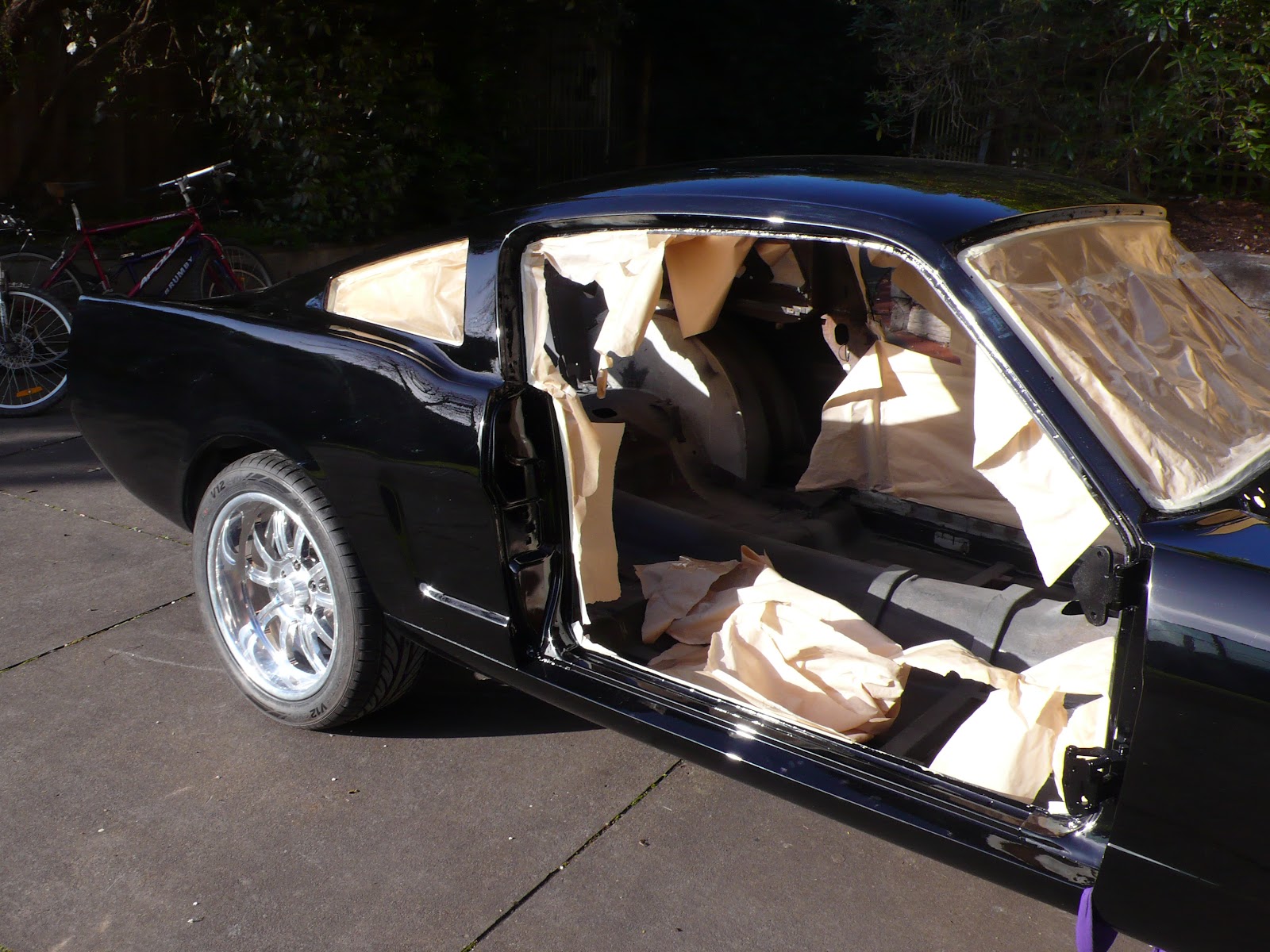
Now that I have the car home from the booth, here are some better photos of the shell.
It caused a bit of fuss driving it home with the Bonspeed wheels on the back as I had a few drivers pulling alongside to have a good look.

The results are pretty good and I'm happy with it. As always, I've managed to find a few flaws (when it's your own car), but nothing major. The biggest pain was a stone ship of all things driving home. I flicked up a piece of wire that nicked the rear passenger qtr-panel (not happy!!). But it is just a spot, not a scratch, so i should be able to touch it up and fix it ok.

So here are the photos of the shell. Keen eyes will notice the extra (almost) 1 inch i got in the rear guards by jacking out the guards before welding the inner wheel-wells to the outer quarter skin.


The fibre-glass bonnet (hood) on the other hand has caused me grief in that I've had to repair some low spots. You will see in the photo below that the front corners of the grafted in 67 scoops were low, as well as where the rear edges "ski jumped" up to meet the correct rear lip contour. This happened because of my custom (removable) upper cowl....... all the cutting and welding changed the height of the curve on the cowl and the rear edge of the bonnet had to be modified to follow it. I've had to insert a painfully tricky hand-fabricated piece of box-tube steel to run right across the back of the bonnet - but inside the rear bonnet frame (which was all fibre-glass) to hide it nicely.


And below is a tease of the final engine build. While the shell was in for painting, I've continued the last few engine details and the dry-sump plumbing got some attention. More on the engine in the next couple of posts.....