Saturday 9 August 2008

Modifying Rotisserie & "Space Frame"

This is just a short post to show the mod's made to the rotisserie that will allow me to complete the chassis & body shell fixes.

Having all the box-tube passing thru to the interior of the car was certainly required when the old chassis (the rusty rails & floor) was cut out, but now that the basic chassis is complete , it can support itself nicely as a single unit. So now I should only need to bolt the rotisserie to the rear bumper mounting bolt holes.

The first thing to do was to put the shell up on blocks (again!!) to take wight off the space-frame as seen below.

From there is was just a matter of cutting the box-tube away and making an inverted A-frame on the rear rotisserie to support the jig that's bolted to the rear bumper mount holes. I used 2mm wall thickness box-tube for these new pieces as the lengths are quite short.


Now I have an uncluttered interior again that will let me install the sub-frame connectors, floor, seat foundations, firewall, etc.

Something to note is that as the front frame-rail (the area under the original battery) is still yet to have its rust hole repaired, I can't bolt a jig up to it and so the space-frame remains at the front of the car. But what does remain is not in my way for making repairs and in fact will be used as a solid base to form a jig that correctly locates the front shock-towers for - when I put in my hidden shock-tower supports. I need to create a custom shock-tower brace as the OEM bracet will very likely get in the way of the big-block's induction setup.

So now its a matter of completing the shell in preparation for installing all the "bolt-on bits". Those bits being the suspension, fuel tank & lines, brakes, wiring, seats, etc.
Completion of the shell will be my next blogg entry as there is significant work to do. But thankfully (in this updated post) "day light saving" has started so i'll have more time to spend on this project over summer.

Friday 25 July 2008

Installing RRS "Notch Kit"

Now that the rear of the car is mostly complete I can move forward to finish the forward sections of the chassis & suspension.
For suspension, I am going to use the local Australian RRS system as this gives me all the required "fixes" I need when installing a big-block in the '66 body. These fixes being......
  • Ability to widen the engine bay.

  • Ability to install modern suspension & brakes.

  • Ability to handle extra engine weight.

  • Ability to reposition "under bonnet" brake plumbing.
I will also be installing a new firewall (a firewall from a modern falcon) to perform a RHD conversion. But when doing so, I will use the opportunity to make room to position the engine as far back as practical to get the best weight distribution I can into the car. When you combine the engine bay mod's made possible by the RRS suspension setup as well as the new firewall mod's - this will be a very different looking (from stock) '66 Mustang engine bay.
Here are some shots of progress.....
Firstly - having cut away the portion of the shock-tower according to the RRS supplied templates. You can see here that the near tower has already been cut away and the paper template loosely positioned on the far shock-tower awaiting proper alignment. No turning back to OEM front suspension now!

The photo below shows the amount of shock-tower "scalloping" that is achieved. You can see that I re-installed the shock tower brace to make sure everything is kept aligned when cutting and welding. Readers of earlier posts will remember that the shock tower shown below had "sagged in" (in towards the engine) nearly an inch over the years. This procedure straightened everything up (back to OEM spec's).

Shown below is some detail of the welding from inside the shock tower. The supplied steel plates from RRS are very solid. I had the MIG voltage turned way up when welding these in!

And below is a photo of the "notch kit" done on both sides. It took about 5 hours all up to do both sides. Fitting the templates and marking the first cut-outs was very quick, but there is quite a bit of trimming & trial fitting to do to get a flush fit all round (and have both sides done symmetrically). This is what takes time and is more of an art/craft. As for just about every little piece of custom work done on this car - if I did it again it would take half the time. Trouble is - i'm only doing everything once!

In the photo below you can see i've trimmed & ground things smooth. You can also see how the base of the notch kit runs almost in line with the frame rails.

And this last photo (taken from inside the passenger compartment - with the old firewall cut out) really gives some perspective of how much extra room there now is.

Soon i'll be able to remove the space frame which will allow me to do a dummy install of the big-block. That will then show me what needs to be done to finish and weld in the new firewall . But fabricating and installing the firewall will be the subject of another post. Stay tuned....

Monday 2 June 2008

Rear Guards & Tail Panel

With the wheelwells finally in place I can start to prepare all the fiddly corners & edged on both the body shell and the new quarter panels to enable them to fit together correctly.

Here is a shot of the rear end after a dummy assembly to see how all the new pieces come together - almost gives enough incentive to continue!
And no, that old couch next to the car is not my bed after the wife kicked me out for spending so much time on the car.....

I've used the method shown in the Mustang Monthly "How To" section under the heading "Quarter Panel Repairs" as my guide on how to do this. Basically, I am spot/plug welding the rear quarters along the front, rear & lower edges - while butt welding the top edge all the way from front to back (back to where the new quarter panel cuts in and joins the trunk drip rail).

However, as both aftermarket quarter panels are not a perfect fit, there is a HEAP of work involved in making sure everything lines up properly from a measurement and aesthetic perspective. This is a warning not to expect a good fit initially!
While the chassis construction was a "build to specification" job by constructing everything according the original engineering drawings, positioning the rear panels is more of an art. There are simply no dimensional measurements I can find that state exactly where (for example) the top outside edge of the rear quarter should be, how high the top edge of the tail panel should be, etc!
A BIG assumption I've made to guide me to where the rear quarter & tail panels should be (an assumption I had to make actually) is that the original trunk lid is very straight and undamaged. If this is true then I figure that if I re-fit the trunk lid to the body shell as perfectly as possible along its upper front edge - then I will have a good guide for positioning the rear quarters to give me the correct panel gaps along the trunk sides (as well as a guide for panel contour, height, length, etc). This is where many many many trail assemblies come in handy as well as an eye for what "looks right".
Here are some shots of various "dummy assemblies" to check panel fit. I had to reshape several edges to make them parallel with the trunk lid. Note that I have temporarily cut away some of my "space frame" and mounted the rear-end (nice & level) on blocks to refit the trunk lid.

I had to "unpick" spot-welds on (both) the rear quarters and reapply them properly to get the panel contours to match the profile of the top edge of the rear quarter extensions.
Notice the major panel gap mismatch between the right-hand trunk edge and the combo' of the rear quarter panel and extension. Lots of work needed to get this gap right!

I also have a "fallback check" in place as I have once again set the bodyshell perfectly level (ie, it is rigidly mounted to the ground at the leaf-spring mounts and wont spin on the rotisserie). This means that no matter what I do on one quarter panel, I can compare its height and width with the other quarter panel to make sure they both end up the same. The following steps need to be done when replacing rear quarters......
  • Repair any rusted supporting panels that the new quarters attach to - to get the foundation right. I fabricated various custom patches for this. I found that the lower door-jams (just above the sills) had small areas that needed patching on both sides. Once patched, the internal faces of exposed metal were painted with Rust Bullet (while the external faces will of course get protected by body paint).

  • Next I prepare any plug/spot-welding surfaces by removing the existing paint primer and replacing it with U-Pol weld-thru copper primer.

  • Next I heated & removed the lead filler that was applied by Ford at the join of the trunk/roof/rear quarters. This is followed by some panel beating to straighten up any edges where I drilled out old spot welds.

  • Next I refit the trunk lid and set the gaps as close to 3/16" as possible ensuring the trunk-lid height was flush with its adjoining front panel (the panel situated between the trunk and the bottom edge of the rear window).

  • Now I could trial-fit the quarters to check/fix panel fit and required panel gaps.

  • I also replaced the trunk "drop offs" as these were cheap to buy, easy to install and provided a perfect new surface to plug/spot weld the lower edges of the new quarters to.

  • For better long-term rust protection I removed the temporary primer from the inside surface of the rear quarters along the lower edges and up over the wheel arch - and coated the bare metal with Rust Bullet.

  • And lastly, I used my trusty measuring tape to make sure (first the chassis and then) both quarters were the same height (above level ground), width (for panel gap and from vehicle centre) & depth (flush with the rear face of the quarter extensions).
Below you can see the inside lower surfaces of the quarters better protected with Rust Bullet.

Notice (below) also that I deviated from OEM spec's along the bottom edge of the tail panel by grafting in some 2mm wall thickness 2" x 2" box tube. This tube solidly ties the rear frame rail together and provides a nice flat surface for spot welding my new tail panel to. The primary reason for the box tube at the rear though was to give the new large capacity stainless steel petrol tank a solid mounting point. The stainless tank is straight out of my old Ute and has a recess in it for fitting the battery (a recess for the battery just like current BMW sedans). This makes the tank/battery combo quite heavy and in need of solid mounting points. This design also keeps all significant rear weight items as low as possible to the ground.

Once the quarters were prepared I tack welded the top front edge as seen below. This makes sure the whole panel doesn't lift at this crucial spot (its right where the door closes and so the panels need to line up). I re-hung the doors as well - as a guide to make sure everything lined up and was a flush fit. In this photo you can see the initial tack welds that i put every 2 or 3" along the top edge of the new quarters in preparation for the final butt-weld. Thankfully, the new panel contour along the top edge was quite close to the original metal profile as can be seen here if you enlarge the photo. And yes, a final patch will need to put into the pillar!
Here is a shot from the rear showing the plug & tack welds. I'm leaving the surrounding old paint and body-filler in place for now to stop surface rust....

And shown below is the other quarter after fully butt-welding the top edge and then smoothed off with the grinder (using a sanding disk). Everything lines up nicely!
With the quarters in place it was time for the tail panel and associated trunk drain channels on the outer edges. I couldn't get my hands on the trunk drain channel corners for a Fastback so I used both the original pieces I cut out and a set of new coupe trunk "drain corners" to fashion new ones - just another few hours of custom fabrication... ho hum.
One thing I did find was that my trunk lid was slightly warped by about 5mm from one rear corner to the other, and, that the final shape of the trunk itself (when shut) is affected by the existence of the rubber seal or not. I had to re-attach segments of the rubber seal to get my final contours right. Lesson - don't remove the rubber seal if going down the path that I did.

Other than that, I had to adjust the section of the rear quarters (where the extensions bolt on) to get the tail panel to sit parallel with the ground. One side was "formed" higher than the other - which is what you can expect with these aftermarket items. As the tail panel was a simple flat sheet of steel (and nice and "square" when measured), it was clear that the back of the rear quarters were the problem.

And here is the result (but not a good exposure I must admit). I've temporarily sprayed any exposed metal with black epoxy primer to prevent rust. Mmmm, maybe a matt-black Fastback would look ok!?

Saturday 10 May 2008

Floor & Rear Wheel Wells

With the full chassis now installed I can cut back on the existing space-frame to free up room to install the floor. I can also now drop the front of the rotisserie back down on the garage floor - as I had chocked the front up on blocks to make the whole shell perfectly level and rigid (for accurate installation of the chassis). See the shot below of the various blocks used to lift the front of the car to a "factory level" position - just prior to chassis installation.
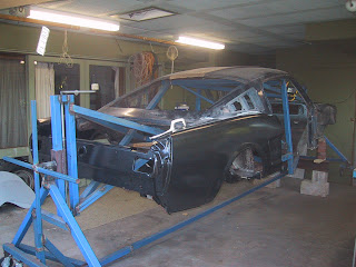
I used factory standard '65 Mustang chassis spec's I found on the Internet to get these measurements right. Something interesting I found with this car was that one side of the roofline (measured at the highest point of the driprail) was about three-quarters of an inch higher than the other side - even when all other frame and sill measurements down to the floor where the same (factory tolerances for 1966 maybe?)! This really surprised me as you just couldn't tell one side was higher than the other when looking at the car (looking at it either before or after dismantling). So I pulled the high-side of the roof down and made sure I corrected all critical body and frame measurements to within about +/- 1 millimeter of factory spec's.

But before the floor actually goes back in and makes it harder to access the whole body shell, I cut out the old rusted front frame extensions, repaired the areas on the front frame where the extensions attached and welded in the new extensions. Here is a sequence of shots showing the extensions being restored.....

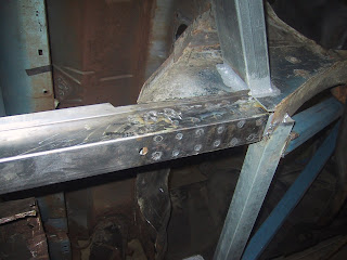
Notice just how many spot welds are done at the factory to hold these extensions on! The shot immediately below shows the extension "stubs" that remained after cutting out the rusty floor - flared open by my cold-chisel after drilling out the spot welds and "enticed" them off.
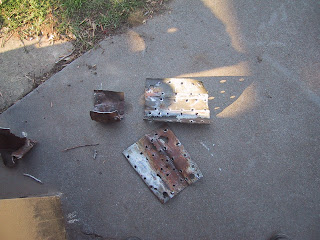
Now notice how much rust protection was done in this area (none!). I cut out the rusty portions of the frames and replaced the cut-outs with new metal.
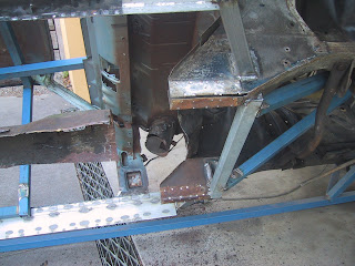
Because the frame-extensions are just a piece of stamped (channel shape) steel and are pushed up as a flush fit under the front frames, moisture gets trapped between the two surfaces around each spot weld. So I've painted the bottom surface of the front frame and the inner surface of the extension with "Rust Bullet". Then I pre-drilled the extensions for the new spot welds, trial-fitted them back on the frame and used a permanent marker to pinpoint where each hole is positioned on the front frame. I then ground away the coating of Rust Bullet at these marks to ensure i had clean metal to perform the spot weld (actually its a Mig weld that simulates a spot-weld by filling up the drill hole in the outer metal sheet). But before mig welding, I sprayed U-POL copper "weld-thru" primer onto each ground-back "spot". I don't think I can do any more to stop rust! The only risk I see is that there is Zinc (in the Rust Bullet paint), Copper (in the U-POL) and Iron in the steel frame - maybe electrolysis can start?..... But surely it's still better than bare metal as found from the factory! Here are the repaired front frames.
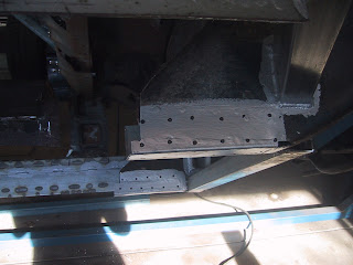
And now the new extensions with the inside surface protected with primer (after drilling the weld holes).
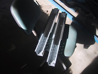
And here is some detail of the finished job. Very strong indeed.
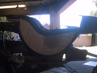
As for the rear wheelwells, I used sheets of cardboard to fashion templates for the 3 pieces used on each side (inner & outer walls as well as the wide strip that forms the "roof"). I was anticipating this was going to be a real pain but it was pretty straight-forward. I first created the inner wall template and used the "spine" that remained from the original wheelwell halves as my top contour and the rear frame-rail as my bottom contour - see picture below (sorry about the background glare).
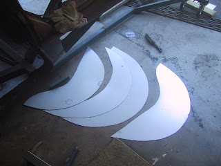
I used the outer guard as my guide to fashion the outer walls and then cut out all the templates. I allowed an extra half-inch or so on each edge in case of error...
After the inner wall was tack-welded in place I once again trial fit the rear guard to fashion the roof section. As I want and original look for the car (no flared guards) the trick here is to give about only half an inch clearance from the outer edge of the roof section to where it would touch the inner surface of the rear guard. This was easy enough to do in iterations as I simply held a permanent marker pen flat against the inner skin of the rear guard and ran it along the edge of the cardboard template. After a few goes of trimming the cardboard back along the marker pen line, the tip of the marker pen no longer touched the edge of the cardboard anywhere when rolled along inside the panel - so job done!
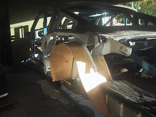
Next thing to do is cut the zinc-coated steel sheet as per the cardboard template and weld it in place. Looks ok in this shot below! I should mention that I took the liberty of moving the diff rebound stops from the outside (wheelwell side) of the rear frame-rail to the inner side. I also positioned the inner wall of the wheelwell inwards as far as possible - so the rear, inner edge of the wheelwell is right up flush against the vertical face of the rear frame rail. I got another inch of width in the wheelwells by doing this - nice (almost tubbed!).
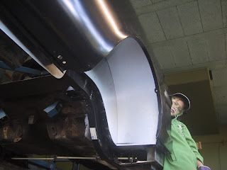
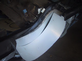
Notice below how the top edge of the inner wall warps once you've welded the (curved) bottom edge. This all straightens up though as you weld the top section on.
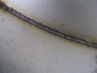
Now just a detail shot of the welds. The Mig does a great job as long as the zinc coating is ground back. There are no pin-holes evident at all. All these weld lines will be rust-proofed of course.
I used the old wheelwell spine and various inside panels to secure the new wheelwells. Some exposed welds look a little ugly now, but they will clean up nicely with a grind-back and primer (plus sound deadener).
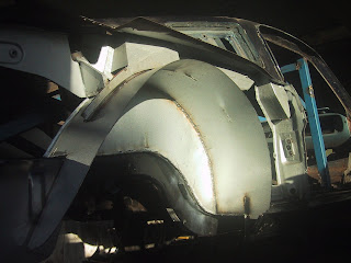
I had to be careful not to extend the new wheelwells too far into the cabin - otherwise I risked not being able to re-install my various interior trim panels. I also had to make sure I kept all mounting points for the interior trim and fold-back rear seat in their correct positions by welding various jig pieces onto the space-frame.
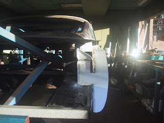
Once both wheelwells had their tops welded in, I re-attached the rear quarters to start the final fabrication of the tricky wheelwell outer walls. At first I cut another cardboard template to try and fabricate the outer wall and inward facing lip (that runs along the inner edge of rear guard that forms the wheel arch) as a single piece - but this proved way too hard. So I cut the lip off the outer wall and then hand-made the lip. I could then clamp the lip to the rear guard for a perfect fit and then tack weld it in place to the outer wheelwell wall before once again removing the rear guard and fully welding the outer wheelwell wall in place. Confused? If so, then hopefully the following pictures of the successful method illuminate things.....
First I tack-welded the outer wheelwell wall to the roof and cut it's lower edge back carefully so that when the rear guard is fitted, the contour of the lower edge fits neatly along the guard lip. There is less than a half-inch gap as you can see below.
Next, use the guard lip to fashion a cardboard template that is then used to cut the metal strip that will become the wheelwell "lip". This shot shows the lip being initially bent over. Hammer & dolly work cleans this up later.
Now I clamp the new lip to the inside of the guard for a perfect fit and tack weld it on. Then I refit the guard (with its included lip in perfect position) and carefully locate the whole guard as if it was being fitted itself for the final time. I then tack-weld the flange of the new lip back onto the wheelwell outer wall (tack weld from inside the wheelwell).
To finish, I grind off the tackwelds that hold the lip to the rear guard - so I can once again remove the guard. This then gives me access to completely weld the lip to the wheelwell from the outside. All that's needed to complete the job is to grind back the welds and cover any exposed raw steel (inside & out) with rust-proof paint.
None of these welds will be visible once the guard is in place so it doesn't have to be pretty. It just needs to have solid welds and have no pin-holes for rust to start.

Saturday 26 January 2008

Body Repairs - New Chassis Installation

While i'm making sure that the rear of the car has been structurally secured, I can start to measure up and weld in place the box-tube that will form the "full chassis". On a standard Mustang, the area where the rear torque-boxes get welded to the inner sills and rear frame, forms a nice hollow void. This "hollow" is right in front of the forward mounting point for the rear leaf-spring. This provides the perfect spot to insert a short piece of box-tube that will connect the rear frame-rail to my new custom length of chassis tube I am running inside the sills. Here is a diagram of where I am adding chassis material to the standard Mustang body.

The areas highlighted in red are the chassis additions (box tube). Tube dimensions are as follows: sill area and sill connection to the factory standard frame rails is 2" X 4" box-tube, sub-frame connectors are 2" X 2" tube. All tube is 2mm wall thickness. The total length of tube added is 3.0 meters for 2" X 2" and 4.8 meters for 2" X 4" tube. This adds just 18kg to the whole body - but improves its torsional rigidity out of site!
Here are some shots of the "sill chassis" being fabricated. With the body shell flipped over you can see the new rear frame rail tack-welded in place and the old inner & outer sill have been completely removed (drilled out the spot welds). As well as removing the bottom-front edge of the old rusty wheel wells....

I fabricated the inner sill out of strips cut from a separate length of 4" X 2" box tube. The gap you can see in the strips is intentional - it gives me a neat gap in the middle of the inner sill (looking from iside the cabin) for welding to the box-tube. This means the box tube is secured to the inner sill not just along its top and bottom edges (when looking from outside the car) but along the middle as well. Very strong!
The new outer sills fit nicely over my new "inner-sill & chassis rail combo", except where the outer sill "necks down" at the front of the car - see below. So I cut the lower edge off the front lower part of the chassis rail, spun it inwards and then welded it back in place. The outer sill now hides my new chassis completely. For the record, the new inner sills are 155mm in height.
Here is a shot of the rear of the sill chassis showing the stitch welding securing it to the inner sills. This is the rear section of the new chassis rails that weld to the front sping mounts (front mounts of the rear leaf springs).

Now (below) you can see the new chassis rail sitting in place with the front edge "inverted" so the outer sill will sit snugly over it. This was just one of many trial fittings.

The shot below shows the new inner sill in place on one side of the car. It is a vast improvement over the old patched-up sills I cut out. In this shot you can see the old rusty sping support & lower torque box still in place on the near side of the car. The new sills will be a perfect foundation to weld the new floor pans to. Check out the holes in the old frame rail at the bottom of the picture!
Where there is a 90 degree bend/join anywhere in the new chassis, I was originally intending to include extra metal to support the join. But there is no need to add the extra metal - it would just be adding redundant weight. With the front of the rear-suspension mounting points welded directly to my new chassis rails, I will nicely distribute the forces being pushed thru the rear axle as evenly as possible throughout the entire car.

This is especially important considering that the big-block up front is heavy, despite being on a diet of various aluminium goodies. Its weight will resist movement when the car accelerates - simply because of its momentum. I have therefore paid special attention to how the new chassis elements mount to the front frame-rails. Any connections pass thru both walls of the existing Mustang front-rails. Welding the new chassis onto just one face of the rail will not distribute the loads evenly and fatigue cracks would eventually occur.

The next few shots shows how I connected the 2" X 4" "sill chassis" to the front frame-rails. The connecting piece runs at an angle to the frame rails to promote strength but still allows plenty of room for larger tyres to fit. This angled connection should not only transmit acceleration forces cleanly to the front of the car but help control twist in the body shell too.

Firstly - measuring about a hundres times before cutting the holes in the frame-rail. The holes in the inner & outer walls of the frame-rail need to be offset from each other as the connecting piece comes in at a slanted angle (not a right-angle) as mentioned. This was tricky to get right!

Trial-fitting the connecting piece.....
Welded in place.... and a perfect fit.
Other side of the car now done too.
Photo from inside the engine bay showing the welding done to complete join.

This shot gives an overall view of the new chassis in place while I "trial fit" it with the outer sills removed. I'll soon be able to remove some of my "space frame" (to install the new floors, etc) as the new chassis is tieing everthing together again.
Below you can see the chassis finally welded in place with sills included.
And below is a shot showing what actually resulted - based on the original drawing I made (at the top of this post). It hasn't varied too far from the drawing. You can clearly see the zinc-coated box tube as it protudes from the front of the sills and connects to the front frame-rail, as well as the rear "stub" that connects to the rear spring-mount.

Not much chassis flex now!

Over and above installation of the "sill chassis", I am also installing the more conventional "sub-frame connectors". As I am replacing the floors and the front frame extensions, it is relatively easy for me (by way of the rotisserie) to install fully welded connectors. These will really tie things together and give me two protected channels within which I can run fuel lines and battery leads from the trunk area up to the engine bay of the car. But rather than weld the connectors to the front frame extentions via pieces of 3mm plate, I am inserting the connectors inside the rail extentions and then welding them in place. Fabricating things this way gets me two nicely protected tubes running from the rear of the car all the way to the engine bay.

Once the chassis is complete i'll be able to install the new wheel-wells (you can see in the photo's that i've alreay started them). The rear panels & wheel wells will probably be the next chapter.