Tuesday 4 December 2007

Engine Part 3 - Ancillaries

The first 2 installments on the engine build for the car should have the reader seeing that this motor is something like the Ford Racing crate engine, the 514. My motor gets to 520 cubic inches because of the 0.030" over-bore.

With the major components covered in the last 2 "engine" posts, this entry concentrates on what parts are needed to complete the motor.

Lets start with the block - here it is all wrapped up as delivered after machine work.


Aftermarket (performance) "385 series" blocks are hard to find here but imported stock "rebuildable" blocks are certainly around. I found a supplier relatively local to me in Melbourne and found what looked like a very rugged block with hardly any lip (worn away by the rings) in the top of the bores. This block had extra castings compared to the others and seemed heavier - all good I thought. Unfortunately, while the block looked good, a crack was found in the valley quite late in the machining process. Not a big one but it would eventually have caused a problem. Thank you machining shop for not just completing it and supplying it to me!! The same shop knew the block supplier and got another one sent over. This time the surface rust in the bore was just too deep (after machining) and some of the elements added to make the casting hard would have been leeched out - making the bore softer. So a third block was sourced and this proved good. Sonic checks of the walls after the 0.030" overbore were good too - I finally had my foundation. Patience pays.
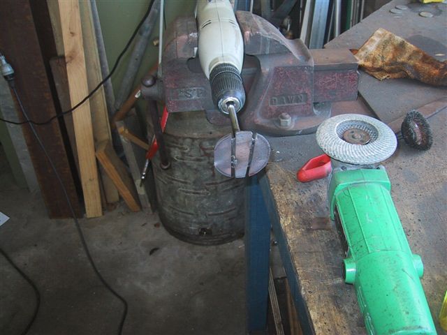
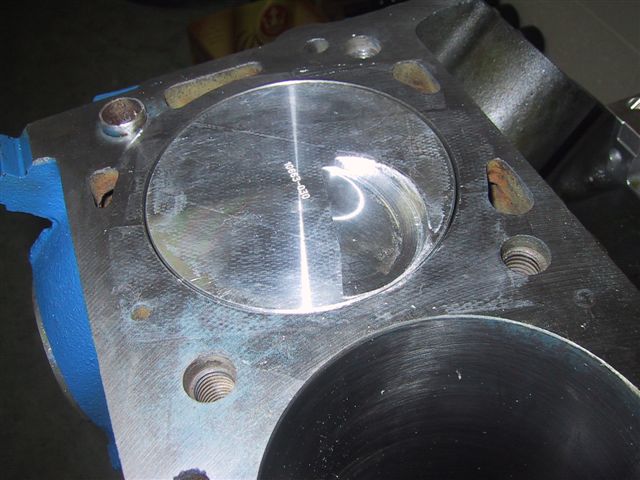
A bare and machined block is just a starting point though. I de-burred and stress relieved all the casting flash I could find and smoothed the oil return passage-ways and internal oil junctions. See below.


I also installed a Moroso oil restrictor kit I retrieved from the 351C. Having a roller-cam and roller rockers means you can safely limit oil going to the lifters and subsequently the whole valvetrain. This ensures the crank & big-ends get priority oiling while the valve-train still gets enough oil for lubrication and heat dissipation. Here is a shot of an oil passage where I tapped and installed a restrictor into. The restrictor is simply a grub screw with a specific sized hole drilled thru it.


Restrictors are installed in bearing saddles 2 thru 5, but only where oil travels from the crank main journal to the camshaft journal - you can see one here in the smaller oil passageway. The larger passageway in the saddle is the main oil supply port from the pump. Be sure to tap a thread deep enough to seat the restrictor below the saddle bearing face. No restrictors should be put in the front main saddle.

While on the oil system, I decided a long time ago that I needed a dry sump. This may sound overkill but I was always having problems with my distributor cam drive gear in the 351C. The steel gear on the roller cam ate up the bronze drives and kept fouling my oil system. I also had the usual oil-surge problems (even with a top of the range baffled sump) that I attributed to the the front oil pickup on Fords. Any right turn while under hard acceleration brought the oil-pressure warning light on! A dry-sump oiling system solves all these issues.

A 3 stage dry-sump pump removes the need to drive a stock oil-pump from the bottom of the dizzy and ensures I scavenge oil from the front & rear of the sump as well as supplying full-pressure oil (no matter what the car is doing) from a remote oil tank. On top of that, I can remove the deep "bucket" area of the sump to lower the sump profile height. This now gives me room at the bottom of the motor to drop the engine slightly lower in the car - if bonnet clearance for the big-block in the early Mustang becomes an issue.


The pump and related pulleys are shown above. Details are: JRP (Jones Racing Products) drive-hub, spacers and pulleys. The drive hub has a serpentine drive-pulley for the future alternator & power-steering pump as well as a radius-tooth drive-pulleys for the dry-sump pump. The 3 stage dry-sump is from Stock Car Racing. All 3 stages (2 scavenge, 1 pressure) are 1.5" wide sections. The vacuum created by the scavenge sections should give me some negative pressure inside the block to help me with ring seal.

You can see the home-made dry-sump I built above. I'm yet to plumb in the scavenge outlets and I am mounting the pump itself on the "oil filter" side of the motor. Fine stainless-steel mesh (from tea strainers) cover the scavenge outlets as a first line of defence from metal particles. A mesh windage-tray is mounted to the crank girdle to trap flying oil - so it then drains down the angled bottom of the sump and pools towards the scavenge outlets.
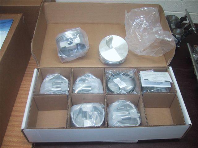
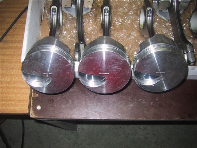
The piston-rings themselves are "medium tension" to help reduce friction and increase available power. The engine bearings are Clevite 77, non hardened - to suit the cast crank. Hardened bearings would have been used if I had a steel crank.
As for the cooling system, I thought about a stock and then even an electric water pump bolted to the front of the motor, but in the end I decided on 2 remote-mounted Davey electric water pumps. This approach frees up the whole front of the block so the camshaft belt-drive will effectively be the front of the motor. This saves a lot of weight at the front of the engine and keeps the centre of gravity well back behind the front wheels. I will have to TIG weld some coolant manifolds to cater for the twin pumps connecting to the single radiator inlet/outlet pipes.

Other items of note are the Felpro "1028" big-bore head gaskets needed to suit the A460 heads (to clear the large valves actually) and the ARP head studs ("SVO" type) to suit the raised inlet and exhaust ports on the A460 heads. You can see that the studs are actually longer on the exhaust side of the block to cater for the much raised exhaust ports!

The cam (mentioned in a previous post) has more than 0.7" lift. I'll keep the specific lift & duration to myself for now until I get the dyno numbers.

As added insurance against harmful engine harmonic, a neutral balance Fluidampr is used and I have had the crankshaft internally balanced. Stroker engines need all the help they can get in this area, but I believe my setup should ensure as smooth a rev range as I can get!

You can see the round slug of mallory-metal pressed into the crank weight at the lower left area of the picture below.

One of the things you find when dummy assembling an engine is shown above. The crank counter-weight is too close to the crank girdle. The girdle will need to be ground away wherever there is less than 0.060" clearance with a moving part.
In summary, what I have tried to do is put a package together where the component parts are complimentary with each other. I will not perform final assembly of the motor until I am nearly ready to fire it up. I want to avoid cylinder and bearing surfaces drying out - which can happen with an assembled motor just sitting around for a long period. As I have no way of knowing exactly when the Mustang will finally be completed, the engine will sit in pieces for now.
I will create another post that details the engine assembly, creation of brackets so the pulleys line-up, installation of the 8 coils that will run in "wasted spark" mode, etc, etc.

Engine Part 2 - Bottom End

With the induction taken care of (at a high level) I had to make sure the reciprocating combination would be up to the task. The great thing about selecting the 460 big block is that parts are comparatively cheap. For example, I found 4340 H-beam conrods cheaper for the 460 than what I could get for a local 351C. Same for the crank and many other parts. Sounds crazy but it is true. I did however find a machine shop who imports without putting a silly uplift on prices. This helps a lot!


For this motor I figured there wasn't going to be any half-measures - I may as well stroke it to gain maximum advantage of the induction. But while stroking an engine builds torque, it lowers the available rev limit because of the mechanical differences it introduces. To counter this I wanted the longest conrods possible to offset the long-throw of the crank. This is needed to minimise the angle of the conrod in the piston at "half stroke" (half-way up or down the bore). The more you increase the stroke the more this becomes a serious consideration. By doing plenty of searching on the internet I came up with the following combo....

  • Cast Scat "460" crank with 4.300" stroke.
  • Crank conrod journals ground down to big-block Chev size - 2.200".

  • Big block Chev, 4340 Chrome-moly' 6.800" H-beam rods with a 0.990" small end (to suite Ford).

  • Probe SRS 4.390" bore forged pistons with a 1.350" deck height.
Here are some shots of the goodies......

Above - the Probe SRS pistons.

The Eagle 6.8" H-beam rods.

The cast 4.3" stroke Scat crank.

The Canton crank girdle - good insurance for a stroker engine.

And the "AustralianMuscleParts" 460 belt drive - a top quality unit. This allows me to modify cam timing in a flash.


Bore & stroke size brings the displacement up to 520 cubic inches (or 8.5 litres).

The crank is just a high-nodular cast iron unit as I saw no huge need to go for anything stronger. It is a very strong unit as is, but yes - a steel crank would have been nice (but much more expensive). Grinding down the conrod journals gives two advantages. 1, allows the use of "Chev" rods - which are cheaper because of the higher manufacturing volumes. 2, the smaller circumference around the smaller conrod journal means a lower velocity across the bearing surface - reducing heat and wear.


The pistons have a short deck height and the gudgeon pin hole cuts into the lower oil-ring land - but this is a trade-off as I wanted the longest rod possible. I guess we will see how much oil control I lose with this setup later (not too much I suspect).

I had to fly-cut the pistons to make the valve-relief required to suite the TrickFlow A460 heads. These heads put the large intake valve in a different position within the combustion chamber so the standard Ford valve reliefs do not match. I initially investigated some machine shops for pricing (quite expensive!) but after researching on the internet I decided to do it myself. The basic principle is this..... Weld a chopped up file onto the head of an exhaust valve, grind it down to size and then use it to fly-cut the pistons. You need to "dummy assemble" the piston and head so your new "fly cutter" cuts the piston crown in exactly the right spot. Here are some shots of the process......


Above - here the file has been cut and welded. The gaps ensure the shavings wont clog things up.

I loosely ground it to shape and then span it in a drill and ground it with an angle grinder to get an approximate shape.

To finish (above), I put it in a Cleveland head (same valve-stem diameter as the 460) and span it in one direction with the drill while using the big grinder which span in the opposite direction. The 351C heads had bronze guides and plenty of lube to ensure a "true" foundation.


Once the new tool was complete it was time to machine the pistons. I setup the tool in just one inlet valve guide in the head and progressively installed each piston in that cylinder. I used masking tape to minimise where the piston shavings could spread - even though the whole engine will be completely dismantling and cleaned before final assembly.


Here is the sequence - but this took quite some time to do for all 8 pistons!

Above - piston installed and masked. Note that I cut away the tape where the cutter would start so it wouldn't clog the teeth on the file.

Lots of filings result after a cut. However, each cut was remarkably quick and easy. Pistons are SOFT!

Above shows the result. You can easily see the inlet valve location difference for the A460 heads.

All done - and each piston is cut the same. The trick to getting them the same is to put in a cutting "stop" on top of the valve guide. This lets the drill only push down a certain distance until it hits the "stop" (a bunch of washers that gives the inlet valve at least 0.060" clearance in the valve relief). And how do you measure that gap?....... You put plasticine on the piston, put the cam in the engine (with a lifter, pushrod, roller rocker and make sure it is timed correctly) and give it a couple of revolutions. Then pull off the head and slice into the plasticine with a razor and measure the plasticine thickness right where the intake valve squashed it. If no slice is less than 60 thou' then you should be ok. I gave myself a little extra room in case I put in a bigger cam, change the cam timing and/or have a longer duration cam later.


Needless to say, this all takes time! Oh - and you have to check the exhaust valve for clearance too. Thankfully, no cuts were needed for them.

That just about wraps it up for the bottom end. There are still a few bits to fabricate in the sump and for brackets to mount the alternator, etc - but these will be done when the engine sits in the car so I know exactly what room I have to work with.

Friday 30 November 2007

Engine Part 1 - Induction System

While I work on the chassis and get enough progress done to warrant another post, here is some info on what has been happening before the Mustang was even thought of - and now continues in parallel with it.

For the last few years while I haven't had a car, I've been slowly putting together the pieces for a new motor. This may seem a little "cart before the horse" but I had my reasons as follows...... When child number 3 came along the ute simply wasn't appropriate any more. The ute itself was fine, it's just that we couldn't all fit in it! As it had so many "go fast" goodies installed, I ripped all the running gear out and sold the shell. Sadly, this left me with just a 351C sitting there in the garage and by this time it was a bit "tired" too. I satisfied my need to tinker by stripping it down and cleaning up the EFI system. The 351C always went well off the mark, bogged down a little in mid-range, but then came on strong again above about 4500RPM. "Bogged down" is a relative thing though - it still went hard, just a little less so in mid-range. It seemed obvious to me that eight 50mm throttle bodies would cause this as the intake runner velocity would be slow until higher RPM's in a 6litre V8 (at wide open throttle - WOT). The EFI injector spray pattern masked the problem with good fuel atomisation off-the-line, but the mid-range at WOT exposed things. Here is the EFI setup I used.....

I made the manifold from 5mm plate and hand-formed the bends. Then I made a steel jig to minimise warpage and TIG welded the lot together. I had to use thick(ish) gaskets between the head and manifold to remove vacuum leaks but other than that it worked great. The design allowed the injectors to have a straight shot down the 351C intake runner. You can see the cold-air box sitting on the table behind. It was nice and low profile to keep everything under the bonnet but gave plenty of room for airflow to the trumpets.

In order to address my suspected "low velocity in the intake runner" problem, the only solutions I saw were either to drop back the number of throttle bodies (eg, use two of the "duel webber" throttle bodies) or use the existing induction on a much bigger engine. As I already had the "quad webber" EFI induction system and I had the Autronic EFI system that can manage all 8 cylinders individually - I decided on a Ford big-block. I chose to go with the newer "385 series" 429/460 cubic inch over the "FE" 427/428 because the parts I would need are cheaper and more easily available in Australia. The first bits I got were the heads. I decided on TrickFlow A460's as they flow really well and would compliment my "quad-webber" induction. Here are the heads as landed in the box from Summit Racing.....


They have huge valves, good springs (for a roller cam), titanium retainers and the intake and exhaust ports are nicely raised to avoid the typical Ford problems of tight bends in the runners.
See above, there is a nice straight shot at the back of the intake (and even better for the exhaust) valves - no nasty bends here!

All I need to do is build a "transition port plate" to mate the outlet face of the throttle bodies to the intake face of the heads. The technical folk at TrickFlow very nicely sent me the intake-face spec's for the A460 head so I can use these as input to a CAD program. The bottom of the throttle bodies are a simple webber pattern. By "morphing" in a CAD program from one port shape to the other (from the circular outlet of the throttle-body to the rectangular intake on the heads) within a 20 or 25mm block of aluminium, I should be able to build the correct configuration file to feed into a CNC milling machine. I soon discovered that while this is nice in theory - I simply cannot find a CAD/CAM package right now that can "easily" do this for me. I've tried lots of sample packages found on the internet - but none make this an easy task. If anyone out there knows of a package that can do this then please let me know. As I only need to create one "drawing", I don't want to have to pay for a whole package.... My backup is to simply hand-form each plate with my drills, die grinder, thread-tappers, etc - but this is messy, time consuming and both plates will be slightly different no matter how careful I am. CNC produced plates would be exactly the same and have a better surface finish.

Compared to the 351C manifold I welded together - which had the throttle-bodies sitting up above the motor and facing upwards, I intend to have the big-block induction runners come straight out perpendicular to the intake face on the heads and "cross over" each other. This means each runner hardly has a bend and allows the whole system to be the lowest profile possible (for fitting under the standard bonnet). I'll be building a single or duel cold-air intake plenum(s) that will sit just above each rocker cover. The plenum(s) will be fed cold and filtered air from behind each headlight. The whole package needs to fit under a 65/66 Shelby style bonnet - that being the fibreglass bonnet skin and scoop grafted to the standard metal bonnet frame.

Here are some photo's that compare the heights of the intake systems when crossing or not-crossing the intake runners. A lot of vertical space is saved by crossing the runners!
Note that the above "crossed" setup is yet to include the "transition port plate" and there are no intake extensions enabling the trumpets to cross.
My final system will have the trumpets on each bank crossing each other by 50mm or so, so opposing trumpets don't steal air from each other - as would happen in the above photo.

Lastly, as the 50mm ports on the throttle bodies are quite a bit smaller than the intake port on the heads, there is potential for the intake charge to slow-down and "tumble" - if transitioning too quickly from the circular throttle-body to rectangular intake port. To avoid this I am going to insert "inlet tongues" to fill the lower portion (just the first half) of the A460 intake ports. The final design will have the intake charge following the roof contour of the intake runner in the head - for maximum speed and minimal turns.
Once completed, this induction system should be the equal of any going around.

Wednesday 21 November 2007

Going for a spin

I had always thought a hoist was the only option for working under a car - until I saw a "vehicle rotisserie" recently in a car mag'. This just made things look too easy so I had to have one. I assumed it would cost quite a bit so I went out and bought the steel, threaded rod, a few large steel washers and a nylon cutting board - as the component parts.

On a couple of mornings where I woke up early, I just thought about how to build it and the results are as you see in the pic's below. First problem was how to make an "adjustable centre of gravity" mechanism. It is no good just bolting the body to a spinning axle - as I am going to first remove a heap of floor metal and then add a heap of box tube for the new chassis. This means the car body would "pendulum" over on its roof as the floor got lighter, and then the opposite would happen as the chassis went in. All this making it much harder rotate by hand when it was out-of-balance at any particular progress point.

So first the adjustable "centre of rotation" sleeves were built...

Basically, this involves welding the round pipe (which is to be the rotisserie "axle") to a metal sleeve that can run up and down outside some box-tube steel. See the picture below.

Notice that i've welded some decent nuts to the sleeve so that when I spin the threaded-rod the sleeve moves along. The threaded rod can only spin (can't slide) as i've welded decent washers to each end. Skate-board wheels make a great handle and as you can see I gave the handles plenty of leverage (length).
Additionally, I cut up a nylon cutting board and inserted slabs of it into the sleeve so that they run smoothly run up and down the tube. No metal on metal grinding here!
The sleeves get about 800mm travel via the threaded rod - plenty to adjust the centre of gravity of the car shell as I remove and add metal (weight) as I work on it.

There are in fact 4 pieces of nylon at each end of the sleeve separated by plywood "spacers".

Next I needed to make the frame that supports the sleeves. There is an "A" frame at each end, trolley wheels so I can move it all around and a length of box-tube to tie each "A" frame together. See below....

The sleeve axle is simply supported in the "A" frame by a custom made "cup". The cup being another piece of 2" pipe, but cut in half lengthways and opened up slightly for a snug fit. I've G-clamped the sleeve axle to the "A" frame cup in the photo above.

I figured the easiest way to put the shell onto the rotisserie was to jack the shell up to what looked like the right height - and then weld it on. See the photo below. I'm sure WorkSafe would have just loved my temporary stands, but the whole thing was actually very stable.

Now this is a very important bit. As I am going to cut out heaps of the floor, sills, torque-boxes, do frame-rail repairs, etc, etc - I can't just bolt or weld the body shell to the sleeves at each bumper - as the body shell will sag and bend in the middle when I try and spin it. I have to build a rigid "space frame" inside the car and weld it to the body-shell at multiple points. The space frame has to be rigid thru a full 360 degree rotation so multiple diagonal struts need to be included.

The first bits I did are seen below - diagonals from the top of the rear sleeve, passing down to each inner sill and incorporating bolts to firmly connect to the rear shock mounts mid-way. There are no instructions for this. I just made it up as I went along. Hopefully some "common sense" crept in at times. The wooden "jigs" you see below are holding the first of the next set of diagonals - coming from the bottom of the sleeve up to the roof.
Also - note that I had to cut out large parts of the rusty floor first - to be able to get to the points on the sills where I had to weld to the space-frame.

OK - here (below) is the rear sleeve all welded up. Note that the body shell is still sitting on its stands - and my little helper just has to be a part of the action.

Time now to run diagonals up to the front sleeve - see below. These are quite long pieces so I used 2mm wall tube for these to reduce anticipated flex.

Here is a closer shot of the diagonals reaching the front sleeve - see below.
You can see the sleeve axle is just sitting in its "A" frame cup.
For the record, tube dimensions are......
All tube is 50mm square box section.
"A" frame and sleeves are 3mm wall thickness.
Space frame is 1.6mm wall - except for upper longer lengths running to front sleeve which are 2mm wall thickness.

Here you can see that i've removed the stands and the shell now spins. Note the angle it went to - it must be heavier on one side (or I didn't weld it exctly in the middle). I actually suspect there is more frame rust (less metal) in the side that sits higher - hence the lean. This shot also shows the "captains wheel" I welded on to the sleeve axle to make it easy to spin the body.

And below is the first time I rolled it out to spin it. However, a design flaw was evident in that the space-frame struts sticking out under the sills hit on the box tube connecting the front and rear "A" frames. Bummer, more work!

So I modified (shortened) them as seen below. Now it spins 360 degrees for easy access to the whole shell. The adjustable sleeves are fantastic. I can shift the centre of balance to be neutral so that it's balanced and spins easily - or I can shift it off neutral to make the shell "pendulum" to an upright or upside down position. I was going to incorporate a locking mechanism to hold the body shell in certain positions - but i've found a simple chock does a great job.

Here (below) is a detail shot of the rear of the rotisserie - nice and structurally sound. No flex is apparent anywhere in a full rotation.

And below is the final incarnation. I lifted the axle "cups" up 2" and had to modify a rear "A" frame brace to clear the body shell tail-lights during rotation. Notice that the trolley wheels are in groups of 2 and pivot in the middle (see the centre bolt for each pair?). This means all wheels carry the same weight even when rolling and the floor is uneven. I figured that if these wheels were solidly welded to the "A" frames then i'd risk a trolley wheel collapsing if it temprarily took too much weight running over a bump.


Now that I can get to all parts of the body I can finally move from the preparation phase to actually restoring & enhancing the car..... but that's for another set of posts......

Friday 16 November 2007

Stripped Down

This post will only partly show how bad the rust is (only showing rust visible from above). The following sequence of shots are self-explanatary............

Here is the Fastback with some Simmons wheels just before the engine came out - not too bad.


Check this out! See the pop-rivet holding the rear guard in place? The last major repair on this car was that both rear quaters were replaced. The repairer obviously didn't have a welder so the skins were riveted in place and a great slab of filler used to cover the rivet heads! Bugger.


See the welded-in patch panel for the lower forward cowel. The upper cowel itself isn't too bad.


Front frame under the battery was eaten out by rust. It was very nice of the last repairer to "bog in" a decent piece of plastic to hide it!


Now this is one old fuel tank. I need a new seive - this may come in handy.


Both rear fender aprons were patch welded back to the shock towers - dodgy job though.


Now this is a bigger problem. Notice the kink in the (American) passenger side fender aprons when compared to the driver side. The passenger side shock-tower has moved in half an inch or so. No doubt due to years of the underlying frame rail being eaten by dilute acid from corroded battery terminals.... The shock-tower support (to the firewall) was probably supporting it more than the frame!


All empty!


Lots of rust in the rear torque-boxes. Both will need replacing.


But everthing around the windows, doors, roof, etc is fine.


Now this is a very ugly floor/sill/cowel/firewall junction (well, what used to be a junction).


And here is a shot showing the seat supports are rusted thru too. However these will be replaced with 50mm box tube to tie the chassis together - so they are getting chucked out anyway.


Now it is time to build the rotissiere so I can get to everything easily.....