Monday 19 November 2012

Fuel Tank setup and Manifold Adaptors

Not only is the body coming together, but the fuel supply and engine are coming along too.
Here is a shot of the stainless tank. You will see the battery box at the rear so the battery is recessed into the tank. Not only that but the Bosche EFI pumps are recessed too. Basically, the outer dimensions of the tank will include all fuel elements and the battery (so the EFI pumps, lift pump, surge tank, etc all recessed into or actually inside the tank.
This way, I just bolt up the tank and there is nothing else to make room for in the trunk. I can just install the tank and connect the fuel and electrical lines - and i'm good to go.

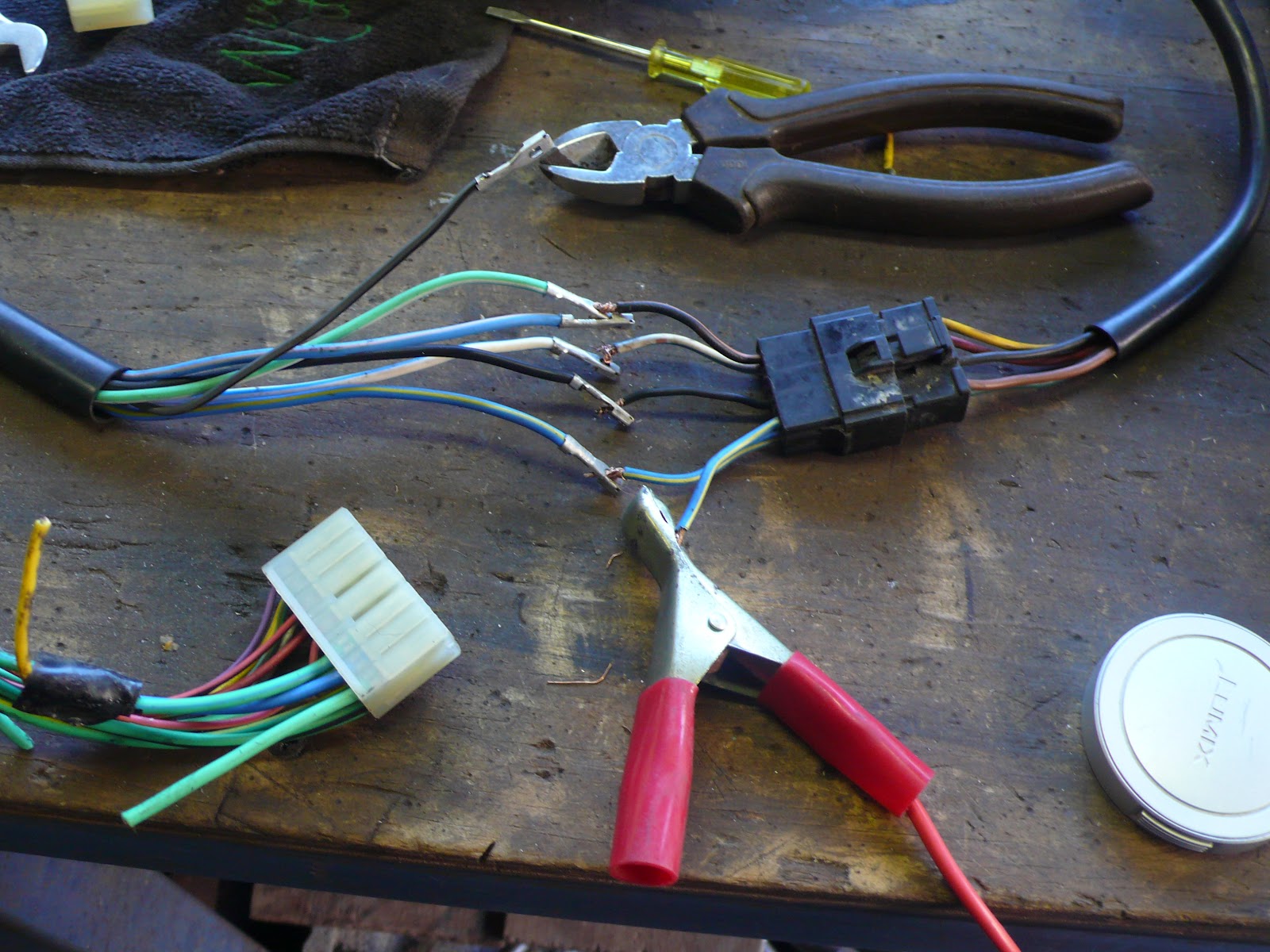
Something that may be of interest is that i'm going to use a PWM output from the EFI management system to provide an input signal to a solid state Hella relay. This will allow me to send a signal to EFI pumps to moderate their speed/output. This is a good thing because it stops the pumps running flat out even at idle (and churning up the fuel). The PWN output is variable based on a map of engine load and RPM. More on this when i finally wire it up.

Now here are some shots of the custom manifold adaptors i built up to convert the circular throttle blocks to the oval ports on the A460 heads. This first shot is from above and shows the 65mm thickness that provides me the port transition required and the 14mm diameter injector bosses.
The photo below shows the head face and the bolt holes along with the coolant ports.
These units have come up beautifully. For anyone local in Australia, i got these machined up at Flexicut in Dandenong by Robbie (owner). It took me quite a while to find a place that had the auto background knowledge and the interest in such a one-off project. I can't recommend them any higher.
The following photo shows the circular inlet compared the oval outlet above.
The coolant outlets are AN-16 thread machined for O-rings.
And the 3 photos below show some test fitting of the injectors and throttles.
Notice the throttle shaft comes close to the injector, but there is room for a throttle position sensor (just) on top of one throttle block. I'll just have to include some little extensions on these injectors o raise the fuel rail to clear everything. The number 1 priority was to get the injector position and angle right - and fit everything around that afterwards. I'll trim the top of the shafts later and create some cover plates to make it all look good.
Of course now i need to sort out my trumpets without having one cylinder steal air from another.....
But it's going to look good and flow plenty of air once done i believe.
And there is the small matter of all the linkages, bell-crank, etc. Yet another mini project that will take time.  

Paint - Test panel fit

Quick update for any viewers....
Decided to do my first panel test-fit after running the brake & fuel lines in the trans tunnel and along the diff' (see below).


I also wired up the tail lights (LED's) and wrapped up the rear loom for wiring up the lights, but i also included some CAT-6 LAN cable for any future IP devices (like a camera) and some extra wiring to control fuel pumps, relays, remote trunk lock, etc.
So - I first fitted the diff, front suspension (yet again) and wheels....
 
Oh - and the seats as well so i could position the new hand-brake correctly. That being a console mounted unit that will be simpler and work heaps better than the dash mounted standard version.
As you can see below - it looks ok....

Thankfully, the bonnet fits really well as the rear edge has a custom curve in it now. It's hard to see here, but the mod's i did on the upper cowl changed the curve (higher in the middle) and it took a lot of work to re-curve the rear edge of the bonnet to match.

But all the panel gaps are pretty good now - so i have to be happy with that.

 Engine update shortly.
 

Sunday 26 August 2012

Home from the Paint Booth

This is just an interim update:
The bonnet & upper cowl returned on the weekend after final paint and they look good.
The bonnet is so much better now than when i first got it, so all the hard work paid off. Compare these photos with the one at the bottom of this post to see the big difference. Those ski jumps are gone and the 67 Shelby style scoop is smooth across the top now - without the crooked ridge that was originally there. It may give the car a slightly unique look for all i know........ but i do know that I've gained about 4 inches of extra clearance with this bonnet. This is all good news for the big block.

And on that note, I've seen one of my blog pictures referenced in other websites when people are chasing info about fitting a 460 engine into an early Mustang.
Yes it is a close fit for me, but any "normal" big block would have even more spare room for an easier fit. In my case I have the Trickflow A460 heads with raised inlet & exhaust ports, plus the tallest valve-covers I could find (to clear the stud girdle), etc. So if you go with standard style heads (either original iron or new alloy units) you'll have plenty of room.


And lastly, I've started running the looms. Here is a shot of the rear of the car with the tail lights in. Starting to look like a car finally.
I've put the shell back up on the spinner so I can most easily run all the wiring, fuel lines, brake line, etc.


Now that I have the car home from the booth, here are some better photos of the shell.
It caused a bit of fuss driving it home with the Bonspeed wheels on the back as I had a few drivers pulling alongside to have a good look.

The results are pretty good and I'm happy with it. As always, I've managed to find a few flaws (when it's your own car), but nothing major. The biggest pain was a stone ship of all things driving home. I flicked up a piece of wire that nicked the rear passenger qtr-panel (not happy!!). But it is just a spot, not a scratch, so i should be able to touch it up and fix it ok.

So here are the photos of the shell. Keen eyes will notice the extra (almost) 1 inch i got in the rear guards by jacking out the guards before welding the inner wheel-wells to the outer quarter skin.


The fibre-glass bonnet (hood) on the other hand has caused me grief in that I've had to repair some low spots. You will see in the photo below that the front corners of the grafted in 67 scoops were low, as well as where the rear edges "ski jumped" up to meet the correct rear lip contour. This happened because of my custom (removable) upper cowl....... all the cutting and welding changed the height of the curve on the cowl and the rear edge of the bonnet had to be modified to follow it. I've had to insert a painfully tricky hand-fabricated piece of box-tube steel to run right across the back of the bonnet - but inside the rear bonnet frame (which was all fibre-glass) to hide it nicely.


And below is a tease of the final engine build. While the shell was in for painting, I've continued the last few engine details and the dry-sump plumbing got some attention. More on the engine in the next couple of posts.....

Saturday 11 August 2012

Paint Activity

Finally!
The milestone has been reached where the shell went off to the paint shop.
Liberating feeling actually. I just hope the final price wont cause me too much grief!

As I had bugger all time to get the shell off the rotisserie, panels hung back on, old diff & front wheels put back in, hire a tandem trailer, drive it over, explain all the mod's, etc, etc (all in one morning) - I just didn't have time to take any pictures of the shift.

But here is a photo of the under-carriage after I hit it with a coat POR-15 chassis black (satin black finish). This was layed down over cured ply-eurethane seam sealer and standard POR-15 (in gloss black) paint in all the right places. And yes, I prepped the gloss-black finish as instructed before laying on the chassis black.


The painter now only need to work on the upper (outer) surfaces of the panels.

Monday 7 May 2012

Belated Update - Body & Electrical

A very good friend of mine messaged me the day I had lapsed for 6 months from putting any updates on the blog for this car - thanks for the reminder Grant!

But the kids have demanded sooooo much time recently that progress has been necessarily slow - but not stopped.

Let's get right to it then. Updates are.........
  • I've found a designer to do the CAD drawing for the custom inlet manifold adaptors. These are required to adapt the oval intake ports on the heads to the throttle butterflies as well as for the coolant outlets & bolt mounting patten.
  • Oh yes - that means i'm going with 8 individual 55mm circular throttle bodies.
  • So i'm now not re-using the the 50mm "quad webber" throttle bodies (they just don't line up to the A460 inlet ports and would have been a major compromise). 
  • Picked up a pair of 750HP Bosch EFI fuel pumps (managed by the EMS of course).
  • Picked up a set of 8 custom EV14 injectors (750cc/min, 30degree spray pattern).
  • Completed the tedious/arduous task of swapping the wipers to RHD positions.
  • Setup the wiper motor to sit in the cavity between the upper & lower cowl panels.
  • Oh - and tested the wiper wiring so it all works on low/high speed and intermittent settings.
  • Tested the wipers and adjusted the various linkages so their travel fits the 66 Mustang window (as the motor/wipers are from a newer falcon that had a much wider "sweep").
  • Relocated the seat best mounting points (for lap/sash belts in front and rear seats).
  • Received a full set of new dash gauges (carefully measured to fit suite the car - to suit the look i'm after that is!).
  • Completed the small job of cutting out the whole dash so I can build the custom heater/vent system.
Now for the pictures.........

First a few shots of the wiper relocation for RHD.
This shows the lower cowel with the RHD wiper pivot points grafted in. I've simply left the old mounts in place and will use block-off plates to seal them.


Now a photo from inside the cabin showing the new wiper drive setup. The dash has obviously been removed at this stage. Mounting the wiper motor in the cowel cavity means i had to weld in wiper motor mounts in the cowel and locate a rubber seal in the lower cowel to enable the wiper motor drive shaft to pass thru. My advise is..... drill the drive-shaft hole first, then weld in the wiper motor mounts. This seal needs to work well to avoid drips into the cabin.
Ah - the reason i'm doing this?.....
To free up room under the dash (the rearward mounted engine has cramped things up a bit - up high under the dash) as well as lower the motor noise inside the cabin. Lastly, the wiper motor is now much easier to get to as the motor itself is easily accessible by just lifting the newly removable upper cowel panel.
Last point to make.... the lower windscreen opening (the lower edge that the actual screen sits on) will need some re-enforcemnet seeing the sandwitch of upper & lower cowel plus firewall panel is no longer all there as a welded unit.

And now a (pretty crappy) shot of the upper cowel with the wiper holes relocated and patches sitting in where the old wiper blade drives used to be. This panel is just at the stage where it's about to get it's thin smear of filler before priming.
And here is the reference photo I have of the wiper motor wiring I need to include in the loom to ensure the motor work correctly for low speed, high speed and intermittent. Took a few attempts to get this right as you need to have the wiper motor, wiper control mechanism (the steering column control) and power/earth all connected properly......

Now we have my "dummy engine management system" setup on the bench to make sure the gauges all work and the wiring is tested before I complete the loom and install it under the dash. The dizzy is setup with the 8 trigger points for TDC for each cylinder and it has a single hall-effect sensor in the normal location under the dizzy cap. You normally have only 4 pulses for the cylinder TDC points, but as i'm only using the dizzy (and not the crank as well, I need all 8 points to account for the dizzy normal running at half the rev's that the crank does.....

Just a photo of the gauges. 5" diameter for the tacho and speedo, 2 and 1/8" diameter for the remaining Volts, Temp, Oil Pressure and Fuel Level. All are LED "thru the dial" lighting and have the ability to raise warning signals if readings are high or low (if I decide to program such warnings in). The final dash will be "custom". More on that in later posts no doubt.


And now the new injectors. EV14, custom built, all flow tested to ensure they flow the same amount. About 120HP each at 80% duty cycle. Plenty for me, but the EV14's also allow for excellent low rev (short duration opening) spray pattern & atomisation characteristics.


I seem to have misplaced some extra photos of the Bosch pumps and other bits and pieces acquired. So a good excuse to create a new post soon.
As an added update, I think i've found my painter and will have to shell over to them soon. I have the rear end of the car back to bare metal right now, so that's a good sign this will happen soon (otherwise it will start surface rusting). We are talking days rather weeks for this as you can imagine.