Wednesday 24 August 2016

More Inerior, Engine Clearances and Modified Intake

This is another short update seeing it's been a long time since my last post - and I've received a few prods to create another post. There has been progress, but slowed due to work commitments, family commitments, and of course Winter here in southern Australia.

So the updates are.................
I am very close to competing my interior (dash, gauge cluster, console) and just need to build up some door trim panels. Here are the photos for this:


I formed the sides of the console first out of cardboard from a reasonably solid box and ran this between the front seats, handbrake, and up to the front face of the dash. Each side was unique based on all the mod's done to the transmission tunnel and I could then cut the template a perfect fit to the dash and get the right length I wanted at the rear.


Shown above is a test fit (one of many!). I ended up cutting a bigger hole for the gear stick of course and also included a small raised plate for the shifter boot to stretch around and snap snugly into place.


So above you can see a bit more detail of the instrumentation and console layout. Things to note are:
  • I have warning lights for "high and low' readings on all gauges.
  • Just under the Tacho you may notice an oil pressure and handbrake warning light.
  • The oil pressure warning light cuts the ignition to save the motor.
  • While I have a "Car Alarm/Central Locking system - I don't use a key to start the engine.
  • I have a finger print reader as my key so my teenage kids (or anyone else) cannot start the car.
  • You cannot bypass the finger print reader without re-wiring just about the whole vehicle :-)
  • My fuses are all mounted to the underside of the lid of the console storage box for easy access.
  • There are more stealth secrets I won't reveal. No surprises there.
  • I am trimming the front-face and underside of the dash in matching leather from the seats, while the top of the dash, the cover over the gauges, and the top panels of the console will all be in black leather (stops glare).
This means the beige/camel leather colouring of the seats sweeps around you at seat level (including the door trims), while the top third of the door trim, the dash top and gauge cluster are in black. The black leather also connects to and sweeps down in an uninterrupted manner along the top of the console. I'm imagining it will look ok. I have the leather already - so it better!


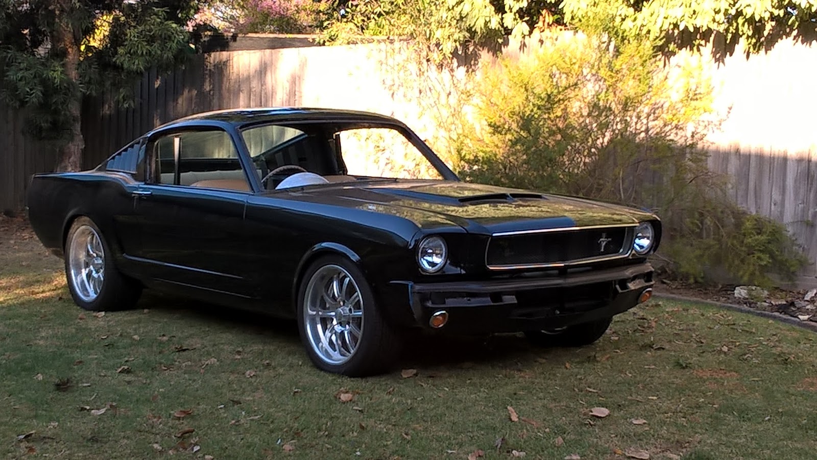
The above photo shows the car as it was a few months back. It is starting to come together nicely. You can see i'm part way thru fabricating my custom front valence and integrated scoop. I have a fair bit of the interior trim installed as well. The seat headrests will be one of the last items going in and the one-piece roof-liner is nearly ready after I installed a 12" LED light bar at the top the rear window as my 3rd brake light. It works a treat.
My door glass is actually in now, but the front wind-screen must wait for my dash to be trimmed in leather before it is installed.
Now for the interesting stuff. My vehicle engineer suggested that I get a bit of extra clearance around the back edge of one valve cover - as I was right on the 10mm minimum limit. See below.....


Yep that is close and could be a problem when the engine shifts when torqued up under load. I could bring the motor forward a bit, but that then takes room I have underneath between the extractors and power steering. I was in a corner and needed to modify things. Now to get at that support to make more room, it would have been a pain to work around the motor... so out the engine came again to do the job right. I get it out of the car on my own in half a day. And scalloping for the extra room required was the easy bit in the end, as I also took the opportunity to adjust the induction seeing I always felt each trumpet could rob air from another. The photo above give you the idea. I therefore did the following:


The above "construction" is a jig I made up so I could fabricate a set of short length, 45 degree bends as induction runners that would bring my trumpets into an upright position. These bends can't be too long otherwise I will run out of room under the hood - and I don't want to break the smooth lines of the current hood by having some great scoop cut into, and sticking out of it. 
What I did was use my CAD/CAM drawing from my intakes and simply used the flat face of the intake that mounts the trumpets as my template. I then had 5mm flat strips of stainless plate laser cut to specification. I only needed 4 plates - 2 each side to sandwich the 45 degree mandrel bends (2.25" stainless tube) I got from the local exhaust shop. The materials were cheap, but it took longer for me to build that dam jig and cut the bends to length, than to weld up (and clean up) the actual runners! 
But the results were worth it - see below.
Will look sweet in the engine bay now (not that looked bad before).


The longer runner will probably help engine performance, and as you can see everything lines up nicely in this last photo. I also have a great foundation now for my cold-air induction box that will use the hood scoops to draw in outside air, then pass that air thru a set of flat filters, which then enters the plenum that houses all the trumpets.

Ok then - until next post. See ya.


Thursday 7 January 2016

Interior Build (and some crazy problems)

Firstly - photos are at the end if that's all you want to see.
Rebuilding an entire car is a big job.....
I blindly started down this road not really understanding how much work I was in for - as once you complete one component to a high standard, the rest needs to follow suit. I'm sure this is not unusual and many others have had the same issue, but if I could cut out "re work" I would be done by now.

You see, we are all good at certain aspects of a rebuild, but not everything. So the things that don't come naturally take extra time/effort or a heap of "rework" to get right.

For example: my nice new Electric Life window actuators. I purchased them as well as the matching wiring looms and chrome switches to make things easier. No such luck. I spent 2 days or more (that means more than 2 weekends) ferreting out a bug that had me truly baffled for a while.
The wiring diagram is nice and simple, you splice the left-hand and right-hand looms together by splicing together just two (same coloured) wires. Easy right? You then run the two pairs of already bundled (blue and black) wires to each motor. Lastly, you connect the red power wire to a fused battery + source and ground the (very obvious) single black earth lead. Wrong! If anyone gets the following symptoms - this may be your problem.
My gremlin was that the passenger side worked fine from either the drivers side or passenger switch, and the drivers side would wind down ok but would blow the power fuse when I try and switch the window "up". If I reversed the wires to the motor the window wound up ok - so the motor is fine. Bad switch I think (even though the switch pins out ok when testing via an Ohm-meter) so I get another, but still the same problem! After much cursing and 20+ blown fuses later, it turns out the earth in the loom went to the wrong terminal that plugs into the drivers side switch. There are 3 black wires in the loom you see (1 earth and 1 for each motor), and somehow at manufacture the black earth wire got swapped with a black motor wire. Easily fixed of course (once diagnosed) by pulling the loom end apart and swapping the two offending black wires at the terminal - but what a complete waste of time. And this is just one example along this journey, it was never going to be easy.

A major recent advance was that I managed to book a visit from my vehicle engineer to do an inspection. It was all good and he found a few items to fix or otherwise look out for. Nothing major thankfully. What I do have to do is relocate my brake biasing valve to "outside" the cabin. This is a compliance rule apparently. Not a hard fix, but fiddly none the less.
Other than that, I just need to ensure I have the mandatory minimum 10mm clearance all around the motor and ancillaries. This includes the headers to steering linkages, dry-sump pump to engine bay, rear of the heads to firewall, exhaust pipes to fuel tank and diff', etc, etc.
I have complete control over this so all good there.

My next inspection will be to have the car go over the pits for its final "exam". This is where all those clearances are checked, the brakes are put thru their paces (they run the car quite hard apparently), noise is checked to be 96Db or below at 3500 RPM, and so on.

Apart from the specific engineering items mentioned above that I need to manage, I've also been able to complete the rear seat area such that I could re-install the rear glass and stainless trim. You really do need to get the complete rear interior finished before putting that window back in - as access is so much easier when it is out. The trickiest bit? Positioning the inner fastback panelling such that any holes drilled into them would line up correctly with my lap/sash seatbelt fastening bolts. The obvious tip is to drill any initial hole very small and gradually expand it as you test fit several times.

Righto - here are some photos that help describe all of the above..........
Starting on re-trimming the rear seats in matching leather.


Test fitting the completed rear seats. You can also see the sound & heat shielding I've installed.


Below are the mounting plates for the shoulder pivot of the rear passenger lap/sash belts.
These babies aren't going anywhere.


And here is how it all looks with the seats, seat belts, and interior panels installed.
I will tighten up the lower seat leather trimming to remove those small wrinkles that you can see in the middle.


And this is how the rear parcel area looks now. Despite the slightly tubbed wheel wells, all the standard seats, trap-door and interior panels remain in place and functional.


In regards to making sure I have all my clearances implemented correctly, this photo gives some idea as to what needs to be done to get a 3" exhaust around a coil-over rear axle setup and make it around the petrol tank in order to exit out thru the standard rear valence. Heaps of work required in all areas! 


The newly re-installed original rear window. This make a big difference to the look of the car.


And a photo of the car outside of the car-port. Starting to get there.


Current activity is to finish off the console, dash, and gauge cluster. This photo gives an idea of where things are at.
All the gauges have been in and tested. I have only removed them to finish the aluminium metal-work needed around the cluster itself. I am also fabricating a glove-box and mounting the heater core.
All this will be in the next post.