Thursday 17 September 2015

Wiring, Lighting (and some "Miscellaneous".....)

In the last month I've managed to get a reasonable block of time devoted to moving this project ahead - thankfully.
Prior to this, work has been ridiculously busy (the hours spent in the office), so this project moves way down the list as a result. However, I took some time off and have now managed to get a bulk of the wiring/electrical work done.
 
In summary, I've managed to complete:
  • Installing the Electric-Life window actuators.
  • Install electric door locks and associated vehicle alarm and keyless remote entry systems.
  • Run all door wiring neatly into the cabin.
  • Locate and mount the engine ECU, CDI Ignition, Alarm, Electric Water Pump controller modules.
  • Locate and mount the master power Circuit-Breaker, Fuses, Relays, Kill-Switches.
  • Run all blinker wiring to the steering column.
  • Graft a late model falcon windscreen wiper switch into the skinny 1966 Mustang steering column.
  • Route wiring for all of the above (including Dome Light control via doors and Car Alarm).
  • Run brake light switch from the brake-biasing valve.
Put into a list like that, it does show I got quite a bit done (and all mandatory items too). As usual though, it's the pictures that I know most folk are interest in - so here they are.
There is probably no point just taking a photo of the electric window and door lock actuators - as they are a simple "bolt-in", it is at the console where it all comes together. So here are some shots of the wiring being bundled/organised in that area.


The electric door lock actuators had me puzzled for a few hours..... They need a full +12v to lock and a full -12 volts to unlock. Theoretically that's a 24volt difference from a 0 to 12v battery. The car alarm system did output this voltage, but it didn't have the grunt to supply the wattage required. If directly connected to the vehicle remote entry control module, the actuators just "oscillated" slightly in either the lock or unlock direction and wouldn't travel the full distance needed. As usual, Mr Google helped me to find a "reverse polarity relay" wiring diagram and this did the trick. The two relays that perform this function are at the upper right of the group of relays shown. They work a treat too. Something else that may be of interest is the solid-state relay at the lower left. This powers my electric water pumps by varying the voltage given to them. It means the pumps don't thrash at 100% power when the engine is cold. Instead, they speed up to 100% gradually as coolant temp rises. I do the same thing for my electric fuel pumps - but based on a PWM signal from the ECU (the PWM is an output that I can elect to track in sync with engine load).  
 
Blinkers. I have not yet had a problem with my early blinker/brake switch combo unit myself, but I read lots of articles about interesting problems that these units cause as they age. I've hopefully avoided such issues by only using the blinker switch for the blinkers and horn, and by activating the brake lights via the pressure switch on the biasing valve. It all seems to work well for now. I could then cut back the brake wiring from the blinker/brake/horn switch by removing the brake wires and then I added the wiring from the newly grafted wiper switch. Just as these photos show.


The wiper stalk is relatively subtle. So I'm quite happy with what I've done here as it seems to be nice and neat and unobtrusive. For those of you who haven't seen an earlier post on this, the late model Falcon wiper switch and motor gives me intermittent, low and high speed wipers (and washer pump) all controlled from the left side of the steering column. I've also moved the wiper motor from inside the cabin to be "inside the cavity formed within the upper and lower cowl panels". Not a small job, but this approach frees up room under the dash and removes all that wiper motor noise from inside the cabin. My upper cowl panel is also now removable so I can service the wiper motor if ever required and properly protect the inside of the cowl from rust.
 Now for the miscellaneous.....
I had a weeping head gasket - dam it! The tiniest of occasional drips occurred at the rear corner of one head after I switched the engine off after a run (when it had maximum heat soak). It must have been from the "water jacket to the outside of the engine", as there was no water in the oil or combustion chamber. This forced me rip out the motor again to fix, so while the engine was out, I did the following - which I had always wanted to do but never had the block of time available:
  • Change the head gaskets, after cleaning up the block and head faces, but this time using Permatex copper head gasket sealant on both sides of the (Felpro 1028) head gaskets.
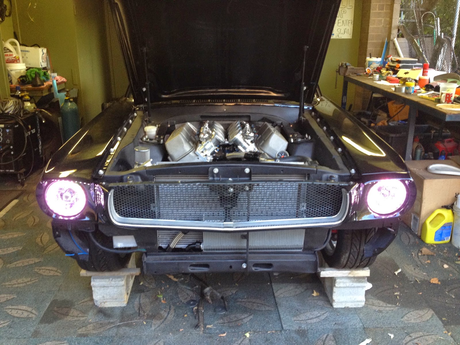
  • Re-contour the bracing at the top of the firewall to give me another inch of room in the engine bay at the back of the motor (to free up more space for induction).
  • Re-contour the inside-top-edge of the shock towers to give me more room where the rocker covers get closest to them.
  • Bite the "financial" bullet and replace the (probably ok) 351C Falcon clutch with a (definitely ok) Centerforce DYAD clutch.
  • Adjust the external dry-sump reservoir to separate the single oil outlet fitting that supplies both the oil level sight tube and the pre-start oil pressure priming pump.
The reason I need to separate the these oil supplies is that the oil priming pump would draw down oil from the site tube and suck air - if the priming pump was run for too long. An annoying issue more than anything drastic to fix.
Here are the relevant photos for all these various tasks........

First the head gasket fix. All I have done is make sure everything is hospital clean again - but this time add the coating of Permatex.


Now for the engine bay mod's. I didn't have to do these changes, but it give me more room.


And now the DYAD clutch addition (dummy fitting stage). I must say, it's an impressive piece and well put together.


The DYAD flywheel is interesting as it has removed a heap of mass from the outside edge of the flywheel. Just look at those CNC machined cut-outs towards the outer edge. This should let the engine spin up much faster (accelerate faster) seeing the original flywheel was a heavy piece with the bulk of its weight on the outer edge. That was a lot of mass "out wide" to rev' up.
 

Friday 27 March 2015

Installation of "Front End" panels and lights.

It's finally starting to look like a real car........With the engine bay now all but complete, I've been able to mount most of the front panels. This includes the upper cowl (that readers of this blog will know is a removable piece on my car now), front guards, hood, headlight buckets and associated wiring/lights, plus the front grill and trim components.
The only things missing are the front bumper, valence (with turn signals) and stone-guard.
This photo shows the current state of assembly.


What is obvious in the above photo is the wider radiator opening and external oil cooler.
But now with the panels painted, refitting them was always going to be the real acid-test in regards to how well the final "fit" would end up. I worked hard in the preparation stage to have constant (neat) panel gaps. But while you do what you can in this area (via mocks ups and adjustments) before paint on the bare body shell, you just never really know how it will turn out with the engine/driveline installed and the suspension loaded up - and this engine is no lightweight! The body and chassis naturally does flex, splay, move around, etc..... Thankfully, by working forwards from the doors, I could still adjust things to a nice neat finish - but it was definitely different from when the car was just a shell.
Here are some photos of the engine bay.


You can see that I've gone with contrasting (Cadmium plated) fender bolts for the front guards and hood latch mechanism. I've also gone with a '65 grille as I prefer that style grille more than the '66 horizontal grille. The headlights are newer H4 halogen units and I've gone the extra mile and used "Halo" headlamps from Redline with the white LED's in the ring around the lamp itself. These LED's within the headlamps will be my "parking lights" rather than using the amber running lights located in the front valence. The amber units in the valence will be dedicated as turn signals. All my lights apart from the low and high-beam headlights are LED's (this includes tail-lights, dash, interior).

Keen eyes may notice that I've modified my front shock-tower supports inside the engine bay so that they can unbolt at the top of the shock-tower load-plate, and pivot upwards from where they mount on the firewall (to fold up against the underside of the hood and be "out of the way"). Space is at a premium around this motor and this adjustment lets me get to rocker-covers, spark-plugs, coils and leads with some sort of dignity.
Now for the front valence. Have a look at this photo of what I have to work with...


With my customised radiator support having such a wide opening, a standard 65/66 Shelby valance/scoop just doesn't work. It would bolt up and fit ok, but with such a narrow inlet, it would block half the airflow I am trying to achieve. So - I'm in the process of combining the standard valence and stone-guard into a single unit, and then I'll graft a custom air scoop into it. I need to be careful here though as changing the front facia of a car can ruin the look very easily. All I can say is that this custom scoop opening needs to be subtle - so it wont poke out forward like a race car, wont be "super low", etc. It will be the width I need though and all metal. Stay tuned.

Other tricks?
I've routed my front wiring from inside the cabin on the passenger side (for Australia remember) and out through the firewall, but up inside the front right fender. As it runs forward in under the front wheel-arches, up as high as possible, all wiring is inside a length of 1" o.d. PVC electrical conduit. This custom "loom" carries wiring for the front turn signals, running lights, high/low beam, auxiliary oil pump power, thermatic fan control, and even a length of CAT-5 (for future IP based camera, security, and functionality options that I have in mind). All this wiring is completely hidden when looking into the engine bay of course to give it a nice neat finish. About the only thing missing within the engine bay now is a final thermo-fan setup. But I've made sure I have plenty of room for it and that can wait for when the car sees some traffic.

The next post will probably be about wiring the dash, installing the instrument cluster, and maybe the beginning of the interior trim fit. Now some additional photos.......


Tuesday 20 January 2015

Engine Bay Completion - Part 2

I jumped the gun with the title of my last post.... To really complete the engine bay, I have some more important tasks to complete such as:
  • Welding up a custom fabricated aluminium external dry-sump reservoir.
  • Install an oil priming pump.
  • Wrap up the starter motor and coil packs in heat shielding.
  • Re-install my shock tower bracing.
For the external dry-sump tank, I am using the space previously used by the battery (which is now in the trunk) as its new location. And seeing that this engine-bay panel had the typical rust associated with a battery leak in a previous life, I have cut out the rust to create a large hole in the spot where the battery tray used to bolt up to. This lets me extend the height of my external oil tank (downwards thru this hole) which gives me advantages in building a tank that efficiently removes air from my scavenged dry-sump oil. Here are some "in progress" photos.


I used a cardboard template to get the outside dimensions done and then added baffles from there. One of which I took a photo of.


Here is a trial fit to make sure the hoses all worked together.


And here you can see how I've cut out the bottom of the battery tray to give the tonk some extra height. Plus include a convenient drain plug.


Never having built one of these things before I did so based on the following thoughts.....
  • Ensure the oil tank outlet is at the lower-rear of the tank (so oil naturally moves towards this outlet under acceleration rather than away from it - and then risk sucking air).
  • Baffle the tank (horizontally) so that oil can't slosh up the back face of the tank and expose the outlet to air.
  • Make the tank itself as high as possible (compared to diameter) so there is a nice column of oil sitting above the outlet.
  • For the scavenge inlet, make this (foamy) scavenged oil-air mix flow over a smooth surface and thru a meshed sieve (similar to a funnel with a sieve filter in the bottom) - to promote air bubbles to come to the surface and "pop" (disappear).
  • Include an oil-level "sight" column, an oil filler neck, drain hole and tank breather.
This tank holds 8 litres when full, but when the engine is running it will  have about 4 litres in it, while the rest of the dry sum plumbing (oil pump, hoses, oil cooler, filter, etc) holds another 4 litres. These next couple of shots show the results of my first prototype. You will see a couple of  blocked off ports that I had to weld over after finding out the radiator hoses got in the way.....


This next bit may be seen as overkill by some, but I've also included a remote (electric) oil pump that allows me to press a "momentary" switch to pressurise the oil system before I hit the start button. In fact, once complete, i'll wire it all up such that the engine wont fire unless there is some oil pressure. I'm thinking that I can use an oil pressure warning light (warning of low pressure) as the trigger to allow the ignition the fire. A benefit is that if I get low oil pressure for any reason while racing and I'm distracted and don't see the warning light - it will automatically cut ignition to protect the motor. A bit of a fail-safe really. This little electric oil pump is just a diff/transmission remote oil cooler pump and wont need to run for any long duration - just long enough to pressurised things until the dry-sump pump takes over. Too easy I say.

One design flaw I've found (that I should have thought of while building the external tank), is that the oil priming pump sucks air through the joint "T" fitting it has with the oil level sigh column. Bummer. I have a couple of options to fix this: either have dedicated separate fittings for both the priming pump and sight level, or, I can insert a small plastic ball into the clear sight tube. For this second option I need a ball that's light enough to float on oil, but small enough so it can just slide up/down within the clear sight-tube, as well as being too big to fit through the lower AN-6 hose-spike fitting. This way, when the priming pump sucks oil (and oil in the sight level drops), this ball drops down to jam against the open end of the hose spike fitting and blocks this passage off. If I can find a "high viz" ball, then this will aid in reading the oil level too.