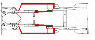
While i'm making sure that the rear of the car has been structurally secured, I can start to measure up and weld in place the box-tube that will form the "full chassis". On a standard Mustang, the area where the rear torque-boxes get welded to the inner sills and rear frame, forms a nice hollow void. This "hollow" is right in front of the forward mounting point for the rear leaf-spring. This provides the perfect spot to insert a short piece of box-tube that will connect the rear frame-rail to my new custom length of chassis tube I am running inside the sills. Here is a diagram of where I am adding chassis material to the standard Mustang body.
This is especially important considering that the big-block up front is heavy, despite being on a diet of various aluminium goodies. Its weight will resist movement when the car accelerates - simply because of its momentum. I have therefore paid special attention to how the new chassis elements mount to the front frame-rails. Any connections pass thru both walls of the existing Mustang front-rails. Welding the new chassis onto just one face of the rail will not distribute the loads evenly and fatigue cracks would eventually occur.
The next few shots shows how I connected the 2" X 4" "sill chassis" to the front frame-rails. The connecting piece runs at an angle to the frame rails to promote strength but still allows plenty of room for larger tyres to fit. This angled connection should not only transmit acceleration forces cleanly to the front of the car but help control twist in the body shell too.
Firstly - measuring about a hundres times before cutting the holes in the frame-rail. The holes in the inner & outer walls of the frame-rail need to be offset from each other as the connecting piece comes in at a slanted angle (not a right-angle) as mentioned. This was tricky to get right!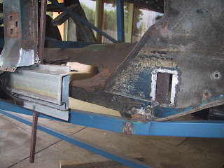
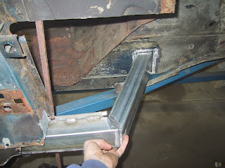
Trial-fitting the connecting piece.....
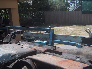
This shot gives an overall view of the new chassis in place while I "trial fit" it with the outer sills removed. I'll soon be able to remove some of my "space frame" (to install the new floors, etc) as the new chassis is tieing everthing together again.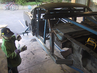
Over and above installation of the "sill chassis", I am also installing the more conventional "sub-frame connectors". As I am replacing the floors and the front frame extensions, it is relatively easy for me (by way of the rotisserie) to install fully welded connectors. These will really tie things together and give me two protected channels within which I can run fuel lines and battery leads from the trunk area up to the engine bay of the car. But rather than weld the connectors to the front frame extentions via pieces of 3mm plate, I am inserting the connectors inside the rail extentions and then welding them in place. Fabricating things this way gets me two nicely protected tubes running from the rear of the car all the way to the engine bay.

The areas highlighted in red are the chassis additions (box tube). Tube dimensions are as follows: sill area and sill connection to the factory standard frame rails is 2" X 4" box-tube, sub-frame connectors are 2" X 2" tube. All tube is 2mm wall thickness. The total length of tube added is 3.0 meters for 2" X 2" and 4.8 meters for 2" X 4" tube. This adds just 18kg to the whole body - but improves its torsional rigidity out of site!
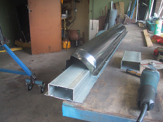
Here are some shots of the "sill chassis" being fabricated. With the body shell flipped over you can see the new rear frame rail tack-welded in place and the old inner & outer sill have been completely removed (drilled out the spot welds). As well as removing the bottom-front edge of the old rusty wheel wells....
I fabricated the inner sill out of strips cut from a separate length of 4" X 2" box tube. The gap you can see in the strips is intentional - it gives me a neat gap in the middle of the inner sill (looking from iside the cabin) for welding to the box-tube. This means the box tube is secured to the inner sill not just along its top and bottom edges (when looking from outside the car) but along the middle as well. Very strong!

I fabricated the inner sill out of strips cut from a separate length of 4" X 2" box tube. The gap you can see in the strips is intentional - it gives me a neat gap in the middle of the inner sill (looking from iside the cabin) for welding to the box-tube. This means the box tube is secured to the inner sill not just along its top and bottom edges (when looking from outside the car) but along the middle as well. Very strong!

The new outer sills fit nicely over my new "inner-sill & chassis rail combo", except where the outer sill "necks down" at the front of the car - see below. So I cut the lower edge off the front lower part of the chassis rail, spun it inwards and then welded it back in place. The outer sill now hides my new chassis completely. For the record, the new inner sills are 155mm in height.

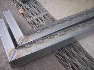
Here is a shot of the rear of the sill chassis showing the stitch welding securing it to the inner sills. This is the rear section of the new chassis rails that weld to the front sping mounts (front mounts of the rear leaf springs).
Now (below) you can see the new chassis rail sitting in place with the front edge "inverted" so the outer sill will sit snugly over it. This was just one of many trial fittings.
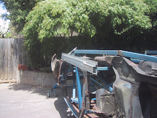
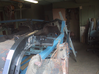
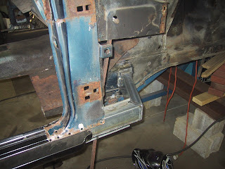
The shot below shows the new inner sill in place on one side of the car. It is a vast improvement over the old patched-up sills I cut out. In this shot you can see the old rusty sping support & lower torque box still in place on the near side of the car. The new sills will be a perfect foundation to weld the new floor pans to. Check out the holes in the old frame rail at the bottom of the picture!

Now (below) you can see the new chassis rail sitting in place with the front edge "inverted" so the outer sill will sit snugly over it. This was just one of many trial fittings.

The shot below shows the new inner sill in place on one side of the car. It is a vast improvement over the old patched-up sills I cut out. In this shot you can see the old rusty sping support & lower torque box still in place on the near side of the car. The new sills will be a perfect foundation to weld the new floor pans to. Check out the holes in the old frame rail at the bottom of the picture!

Where there is a 90 degree bend/join anywhere in the new chassis, I was originally intending to include extra metal to support the join. But there is no need to add the extra metal - it would just be adding redundant weight. With the front of the rear-suspension mounting points welded directly to my new chassis rails, I will nicely distribute the forces being pushed thru the rear axle as evenly as possible throughout the entire car.
This is especially important considering that the big-block up front is heavy, despite being on a diet of various aluminium goodies. Its weight will resist movement when the car accelerates - simply because of its momentum. I have therefore paid special attention to how the new chassis elements mount to the front frame-rails. Any connections pass thru both walls of the existing Mustang front-rails. Welding the new chassis onto just one face of the rail will not distribute the loads evenly and fatigue cracks would eventually occur.
The next few shots shows how I connected the 2" X 4" "sill chassis" to the front frame-rails. The connecting piece runs at an angle to the frame rails to promote strength but still allows plenty of room for larger tyres to fit. This angled connection should not only transmit acceleration forces cleanly to the front of the car but help control twist in the body shell too.
Firstly - measuring about a hundres times before cutting the holes in the frame-rail. The holes in the inner & outer walls of the frame-rail need to be offset from each other as the connecting piece comes in at a slanted angle (not a right-angle) as mentioned. This was tricky to get right!

Trial-fitting the connecting piece.....

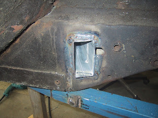
Welded in place.... and a perfect fit.

Other side of the car now done too.
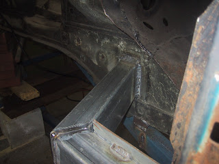

Photo from inside the engine bay showing the welding done to complete join.

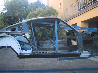
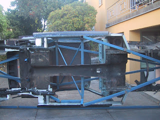
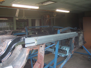
This shot gives an overall view of the new chassis in place while I "trial fit" it with the outer sills removed. I'll soon be able to remove some of my "space frame" (to install the new floors, etc) as the new chassis is tieing everthing together again.

Below you can see the chassis finally welded in place with sills included.

And below is a shot showing what actually resulted - based on the original drawing I made (at the top of this post). It hasn't varied too far from the drawing. You can clearly see the zinc-coated box tube as it protudes from the front of the sills and connects to the front frame-rail, as well as the rear "stub" that connects to the rear spring-mount.
Not much chassis flex now!

Over and above installation of the "sill chassis", I am also installing the more conventional "sub-frame connectors". As I am replacing the floors and the front frame extensions, it is relatively easy for me (by way of the rotisserie) to install fully welded connectors. These will really tie things together and give me two protected channels within which I can run fuel lines and battery leads from the trunk area up to the engine bay of the car. But rather than weld the connectors to the front frame extentions via pieces of 3mm plate, I am inserting the connectors inside the rail extentions and then welding them in place. Fabricating things this way gets me two nicely protected tubes running from the rear of the car all the way to the engine bay.
Once the chassis is complete i'll be able to install the new wheel-wells (you can see in the photo's that i've alreay started them). The rear panels & wheel wells will probably be the next chapter.


