For this motor I figured there wasn't going to be any half-measures - I may as well stroke it to gain maximum advantage of the induction. But while stroking an engine builds torque, it lowers the available rev limit because of the mechanical differences it introduces. To counter this I wanted the longest conrods possible to offset the long-throw of the crank. This is needed to minimise the angle of the conrod in the piston at "half stroke" (half-way up or down the bore). The more you increase the stroke the more this becomes a serious consideration. By doing plenty of searching on the internet I came up with the following combo....
- Cast Scat "460" crank with 4.300" stroke.
- Crank conrod journals ground down to big-block Chev size - 2.200".
- Big block Chev, 4340 Chrome-moly' 6.800" H-beam rods with a 0.990" small end (to suite Ford).
- Probe SRS 4.390" bore forged pistons with a 1.350" deck height.
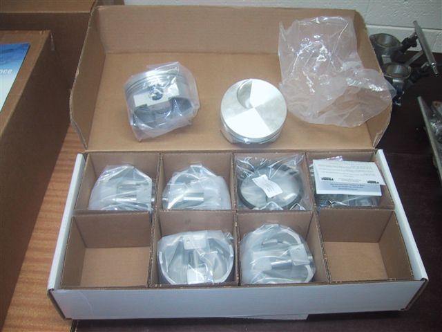
Above - the Probe SRS pistons.

The Eagle 6.8" H-beam rods.

The cast 4.3" stroke Scat crank.

The Canton crank girdle - good insurance for a stroker engine.

And the "AustralianMuscleParts" 460 belt drive - a top quality unit. This allows me to modify cam timing in a flash.
Bore & stroke size brings the displacement up to 520 cubic inches (or 8.5 litres).
The crank is just a high-nodular cast iron unit as I saw no huge need to go for anything stronger. It is a very strong unit as is, but yes - a steel crank would have been nice (but much more expensive). Grinding down the conrod journals gives two advantages. 1, allows the use of "Chev" rods - which are cheaper because of the higher manufacturing volumes. 2, the smaller circumference around the smaller conrod journal means a lower velocity across the bearing surface - reducing heat and wear.
The pistons have a short deck height and the gudgeon pin hole cuts into the lower oil-ring land - but this is a trade-off as I wanted the longest rod possible. I guess we will see how much oil control I lose with this setup later (not too much I suspect).
I had to fly-cut the pistons to make the valve-relief required to suite the TrickFlow A460 heads. These heads put the large intake valve in a different position within the combustion chamber so the standard Ford valve reliefs do not match. I initially investigated some machine shops for pricing (quite expensive!) but after researching on the internet I decided to do it myself. The basic principle is this..... Weld a chopped up file onto the head of an exhaust valve, grind it down to size and then use it to fly-cut the pistons. You need to "dummy assemble" the piston and head so your new "fly cutter" cuts the piston crown in exactly the right spot. Here are some shots of the process......

Above - here the file has been cut and welded. The gaps ensure the shavings wont clog things up.
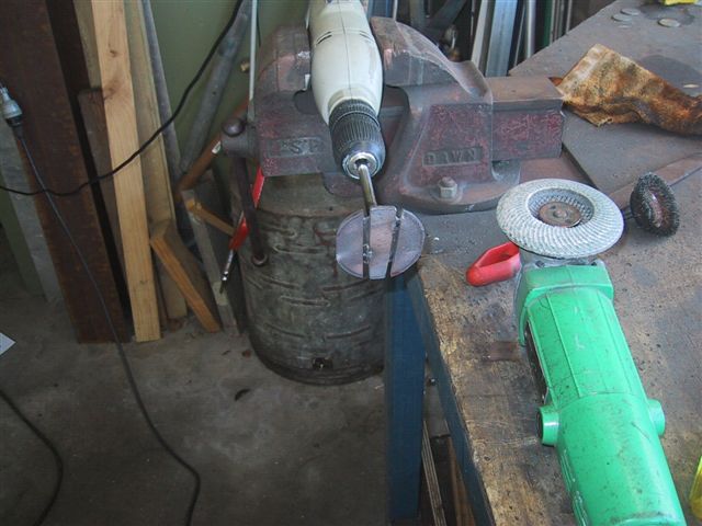
I loosely ground it to shape and then span it in a drill and ground it with an angle grinder to get an approximate shape.

To finish (above), I put it in a Cleveland head (same valve-stem diameter as the 460) and span it in one direction with the drill while using the big grinder which span in the opposite direction. The 351C heads had bronze guides and plenty of lube to ensure a "true" foundation.
Once the new tool was complete it was time to machine the pistons. I setup the tool in just one inlet valve guide in the head and progressively installed each piston in that cylinder. I used masking tape to minimise where the piston shavings could spread - even though the whole engine will be completely dismantling and cleaned before final assembly.
Here is the sequence - but this took quite some time to do for all 8 pistons!

Above - piston installed and masked. Note that I cut away the tape where the cutter would start so it wouldn't clog the teeth on the file.

Lots of filings result after a cut. However, each cut was remarkably quick and easy. Pistons are SOFT!
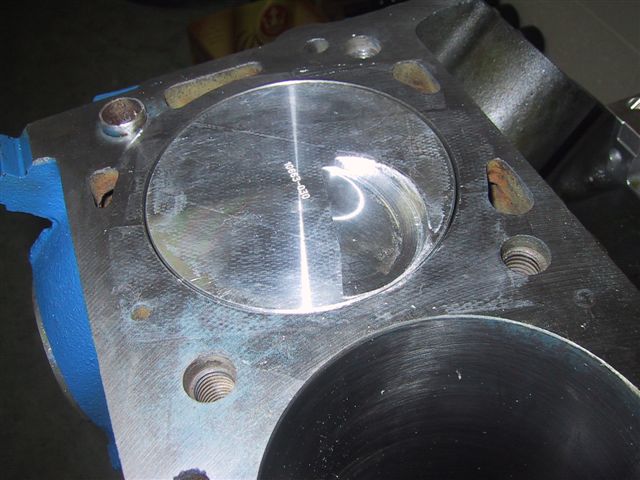
Above shows the result. You can easily see the inlet valve location difference for the A460 heads.
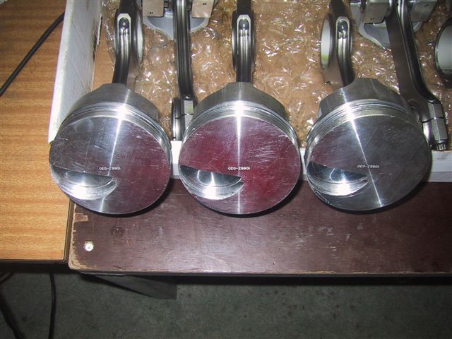
All done - and each piston is cut the same. The trick to getting them the same is to put in a cutting "stop" on top of the valve guide. This lets the drill only push down a certain distance until it hits the "stop" (a bunch of washers that gives the inlet valve at least 0.060" clearance in the valve relief). And how do you measure that gap?....... You put plasticine on the piston, put the cam in the engine (with a lifter, pushrod, roller rocker and make sure it is timed correctly) and give it a couple of revolutions. Then pull off the head and slice into the plasticine with a razor and measure the plasticine thickness right where the intake valve squashed it. If no slice is less than 60 thou' then you should be ok. I gave myself a little extra room in case I put in a bigger cam, change the cam timing and/or have a longer duration cam later.
Needless to say, this all takes time! Oh - and you have to check the exhaust valve for clearance too. Thankfully, no cuts were needed for them.
That just about wraps it up for the bottom end. There are still a few bits to fabricate in the sump and for brackets to mount the alternator, etc - but these will be done when the engine sits in the car so I know exactly what room I have to work with.
No comments:
Post a Comment