Friday 30 November 2007

Engine Part 1 - Induction System

While I work on the chassis and get enough progress done to warrant another post, here is some info on what has been happening before the Mustang was even thought of - and now continues in parallel with it.

For the last few years while I haven't had a car, I've been slowly putting together the pieces for a new motor. This may seem a little "cart before the horse" but I had my reasons as follows...... When child number 3 came along the ute simply wasn't appropriate any more. The ute itself was fine, it's just that we couldn't all fit in it! As it had so many "go fast" goodies installed, I ripped all the running gear out and sold the shell. Sadly, this left me with just a 351C sitting there in the garage and by this time it was a bit "tired" too. I satisfied my need to tinker by stripping it down and cleaning up the EFI system. The 351C always went well off the mark, bogged down a little in mid-range, but then came on strong again above about 4500RPM. "Bogged down" is a relative thing though - it still went hard, just a little less so in mid-range. It seemed obvious to me that eight 50mm throttle bodies would cause this as the intake runner velocity would be slow until higher RPM's in a 6litre V8 (at wide open throttle - WOT). The EFI injector spray pattern masked the problem with good fuel atomisation off-the-line, but the mid-range at WOT exposed things. Here is the EFI setup I used.....

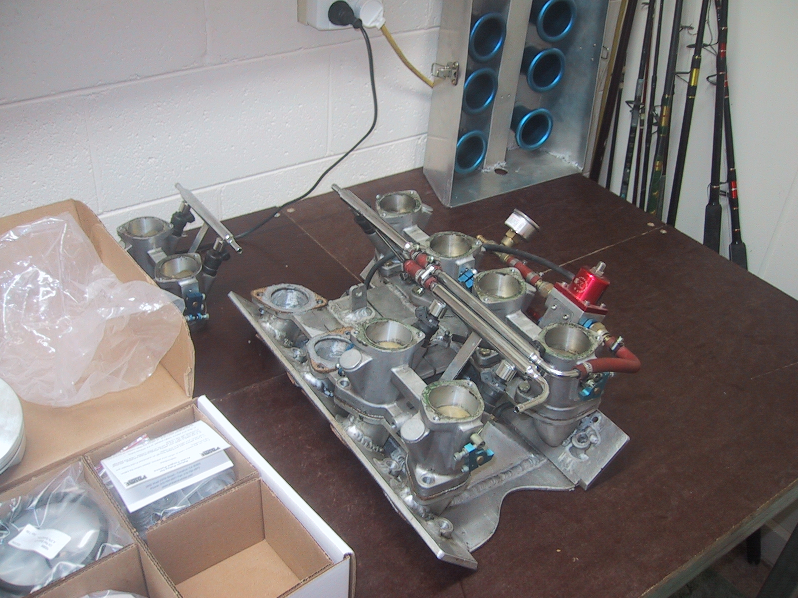
I made the manifold from 5mm plate and hand-formed the bends. Then I made a steel jig to minimise warpage and TIG welded the lot together. I had to use thick(ish) gaskets between the head and manifold to remove vacuum leaks but other than that it worked great. The design allowed the injectors to have a straight shot down the 351C intake runner. You can see the cold-air box sitting on the table behind. It was nice and low profile to keep everything under the bonnet but gave plenty of room for airflow to the trumpets.

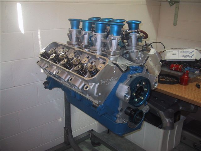
In order to address my suspected "low velocity in the intake runner" problem, the only solutions I saw were either to drop back the number of throttle bodies (eg, use two of the "duel webber" throttle bodies) or use the existing induction on a much bigger engine. As I already had the "quad webber" EFI induction system and I had the Autronic EFI system that can manage all 8 cylinders individually - I decided on a Ford big-block. I chose to go with the newer "385 series" 429/460 cubic inch over the "FE" 427/428 because the parts I would need are cheaper and more easily available in Australia. The first bits I got were the heads. I decided on TrickFlow A460's as they flow really well and would compliment my "quad-webber" induction. Here are the heads as landed in the box from Summit Racing.....


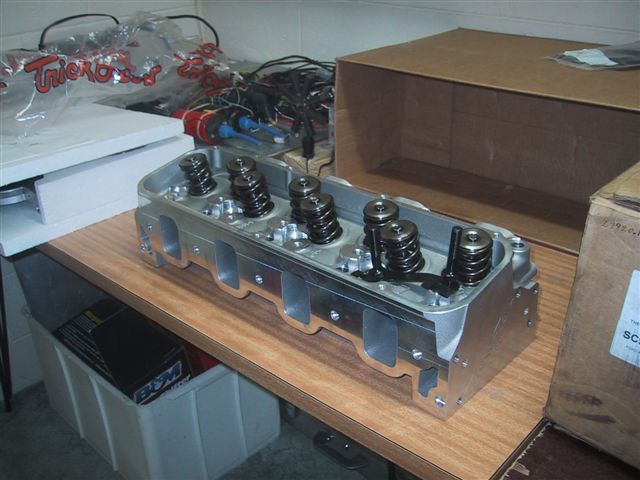
They have huge valves, good springs (for a roller cam), titanium retainers and the intake and exhaust ports are nicely raised to avoid the typical Ford problems of tight bends in the runners.
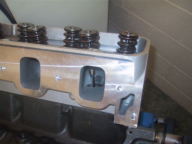
See above, there is a nice straight shot at the back of the intake (and even better for the exhaust) valves - no nasty bends here!

All I need to do is build a "transition port plate" to mate the outlet face of the throttle bodies to the intake face of the heads. The technical folk at TrickFlow very nicely sent me the intake-face spec's for the A460 head so I can use these as input to a CAD program. The bottom of the throttle bodies are a simple webber pattern. By "morphing" in a CAD program from one port shape to the other (from the circular outlet of the throttle-body to the rectangular intake on the heads) within a 20 or 25mm block of aluminium, I should be able to build the correct configuration file to feed into a CNC milling machine. I soon discovered that while this is nice in theory - I simply cannot find a CAD/CAM package right now that can "easily" do this for me. I've tried lots of sample packages found on the internet - but none make this an easy task. If anyone out there knows of a package that can do this then please let me know. As I only need to create one "drawing", I don't want to have to pay for a whole package.... My backup is to simply hand-form each plate with my drills, die grinder, thread-tappers, etc - but this is messy, time consuming and both plates will be slightly different no matter how careful I am. CNC produced plates would be exactly the same and have a better surface finish.

Compared to the 351C manifold I welded together - which had the throttle-bodies sitting up above the motor and facing upwards, I intend to have the big-block induction runners come straight out perpendicular to the intake face on the heads and "cross over" each other. This means each runner hardly has a bend and allows the whole system to be the lowest profile possible (for fitting under the standard bonnet). I'll be building a single or duel cold-air intake plenum(s) that will sit just above each rocker cover. The plenum(s) will be fed cold and filtered air from behind each headlight. The whole package needs to fit under a 65/66 Shelby style bonnet - that being the fibreglass bonnet skin and scoop grafted to the standard metal bonnet frame.

Here are some photo's that compare the heights of the intake systems when crossing or not-crossing the intake runners. A lot of vertical space is saved by crossing the runners!
Note that the above "crossed" setup is yet to include the "transition port plate" and there are no intake extensions enabling the trumpets to cross.
My final system will have the trumpets on each bank crossing each other by 50mm or so, so opposing trumpets don't steal air from each other - as would happen in the above photo.

Lastly, as the 50mm ports on the throttle bodies are quite a bit smaller than the intake port on the heads, there is potential for the intake charge to slow-down and "tumble" - if transitioning too quickly from the circular throttle-body to rectangular intake port. To avoid this I am going to insert "inlet tongues" to fill the lower portion (just the first half) of the A460 intake ports. The final design will have the intake charge following the roof contour of the intake runner in the head - for maximum speed and minimal turns.
Once completed, this induction system should be the equal of any going around.

Wednesday 21 November 2007

Going for a spin

I had always thought a hoist was the only option for working under a car - until I saw a "vehicle rotisserie" recently in a car mag'. This just made things look too easy so I had to have one. I assumed it would cost quite a bit so I went out and bought the steel, threaded rod, a few large steel washers and a nylon cutting board - as the component parts.

On a couple of mornings where I woke up early, I just thought about how to build it and the results are as you see in the pic's below. First problem was how to make an "adjustable centre of gravity" mechanism. It is no good just bolting the body to a spinning axle - as I am going to first remove a heap of floor metal and then add a heap of box tube for the new chassis. This means the car body would "pendulum" over on its roof as the floor got lighter, and then the opposite would happen as the chassis went in. All this making it much harder rotate by hand when it was out-of-balance at any particular progress point.

So first the adjustable "centre of rotation" sleeves were built...

Basically, this involves welding the round pipe (which is to be the rotisserie "axle") to a metal sleeve that can run up and down outside some box-tube steel. See the picture below.

Notice that i've welded some decent nuts to the sleeve so that when I spin the threaded-rod the sleeve moves along. The threaded rod can only spin (can't slide) as i've welded decent washers to each end. Skate-board wheels make a great handle and as you can see I gave the handles plenty of leverage (length).
Additionally, I cut up a nylon cutting board and inserted slabs of it into the sleeve so that they run smoothly run up and down the tube. No metal on metal grinding here!
The sleeves get about 800mm travel via the threaded rod - plenty to adjust the centre of gravity of the car shell as I remove and add metal (weight) as I work on it.

There are in fact 4 pieces of nylon at each end of the sleeve separated by plywood "spacers".

Next I needed to make the frame that supports the sleeves. There is an "A" frame at each end, trolley wheels so I can move it all around and a length of box-tube to tie each "A" frame together. See below....

The sleeve axle is simply supported in the "A" frame by a custom made "cup". The cup being another piece of 2" pipe, but cut in half lengthways and opened up slightly for a snug fit. I've G-clamped the sleeve axle to the "A" frame cup in the photo above.

I figured the easiest way to put the shell onto the rotisserie was to jack the shell up to what looked like the right height - and then weld it on. See the photo below. I'm sure WorkSafe would have just loved my temporary stands, but the whole thing was actually very stable.

Now this is a very important bit. As I am going to cut out heaps of the floor, sills, torque-boxes, do frame-rail repairs, etc, etc - I can't just bolt or weld the body shell to the sleeves at each bumper - as the body shell will sag and bend in the middle when I try and spin it. I have to build a rigid "space frame" inside the car and weld it to the body-shell at multiple points. The space frame has to be rigid thru a full 360 degree rotation so multiple diagonal struts need to be included.

The first bits I did are seen below - diagonals from the top of the rear sleeve, passing down to each inner sill and incorporating bolts to firmly connect to the rear shock mounts mid-way. There are no instructions for this. I just made it up as I went along. Hopefully some "common sense" crept in at times. The wooden "jigs" you see below are holding the first of the next set of diagonals - coming from the bottom of the sleeve up to the roof.
Also - note that I had to cut out large parts of the rusty floor first - to be able to get to the points on the sills where I had to weld to the space-frame.

OK - here (below) is the rear sleeve all welded up. Note that the body shell is still sitting on its stands - and my little helper just has to be a part of the action.

Time now to run diagonals up to the front sleeve - see below. These are quite long pieces so I used 2mm wall tube for these to reduce anticipated flex.

Here is a closer shot of the diagonals reaching the front sleeve - see below.
You can see the sleeve axle is just sitting in its "A" frame cup.
For the record, tube dimensions are......
All tube is 50mm square box section.
"A" frame and sleeves are 3mm wall thickness.
Space frame is 1.6mm wall - except for upper longer lengths running to front sleeve which are 2mm wall thickness.

Here you can see that i've removed the stands and the shell now spins. Note the angle it went to - it must be heavier on one side (or I didn't weld it exctly in the middle). I actually suspect there is more frame rust (less metal) in the side that sits higher - hence the lean. This shot also shows the "captains wheel" I welded on to the sleeve axle to make it easy to spin the body.

And below is the first time I rolled it out to spin it. However, a design flaw was evident in that the space-frame struts sticking out under the sills hit on the box tube connecting the front and rear "A" frames. Bummer, more work!

So I modified (shortened) them as seen below. Now it spins 360 degrees for easy access to the whole shell. The adjustable sleeves are fantastic. I can shift the centre of balance to be neutral so that it's balanced and spins easily - or I can shift it off neutral to make the shell "pendulum" to an upright or upside down position. I was going to incorporate a locking mechanism to hold the body shell in certain positions - but i've found a simple chock does a great job.

Here (below) is a detail shot of the rear of the rotisserie - nice and structurally sound. No flex is apparent anywhere in a full rotation.

And below is the final incarnation. I lifted the axle "cups" up 2" and had to modify a rear "A" frame brace to clear the body shell tail-lights during rotation. Notice that the trolley wheels are in groups of 2 and pivot in the middle (see the centre bolt for each pair?). This means all wheels carry the same weight even when rolling and the floor is uneven. I figured that if these wheels were solidly welded to the "A" frames then i'd risk a trolley wheel collapsing if it temprarily took too much weight running over a bump.


Now that I can get to all parts of the body I can finally move from the preparation phase to actually restoring & enhancing the car..... but that's for another set of posts......

Friday 16 November 2007

Stripped Down

This post will only partly show how bad the rust is (only showing rust visible from above). The following sequence of shots are self-explanatary............

Here is the Fastback with some Simmons wheels just before the engine came out - not too bad.


Check this out! See the pop-rivet holding the rear guard in place? The last major repair on this car was that both rear quaters were replaced. The repairer obviously didn't have a welder so the skins were riveted in place and a great slab of filler used to cover the rivet heads! Bugger.


See the welded-in patch panel for the lower forward cowel. The upper cowel itself isn't too bad.


Front frame under the battery was eaten out by rust. It was very nice of the last repairer to "bog in" a decent piece of plastic to hide it!


Now this is one old fuel tank. I need a new seive - this may come in handy.


Both rear fender aprons were patch welded back to the shock towers - dodgy job though.


Now this is a bigger problem. Notice the kink in the (American) passenger side fender aprons when compared to the driver side. The passenger side shock-tower has moved in half an inch or so. No doubt due to years of the underlying frame rail being eaten by dilute acid from corroded battery terminals.... The shock-tower support (to the firewall) was probably supporting it more than the frame!


All empty!


Lots of rust in the rear torque-boxes. Both will need replacing.


But everthing around the windows, doors, roof, etc is fine.


Now this is a very ugly floor/sill/cowel/firewall junction (well, what used to be a junction).


And here is a shot showing the seat supports are rusted thru too. However these will be replaced with 50mm box tube to tie the chassis together - so they are getting chucked out anyway.


Now it is time to build the rotissiere so I can get to everything easily.....

Thursday 15 November 2007

Round the block

Now that I knew the engine ticked over, I checked the brakes and auto to see if I could take it for a spin. The fluid level in the gearbox looked ok (a bit strange seeing a trans-cooler hose was disconnected when I got it) and the brakes worked when I rolled it off the trailer and then again when I rolled it down the driveway. So the driveline/brakes looked initially sorted


I got some imperial welsh plugs and some "cheapo" rocker covers to complete the engine, but christ - what a pain it is to put in rear welsh-plugs (in a power steering equiped 289)! It took me several hours as you can't get a straight hit on a drive dolly to seat the rear welsh plugs. After many skinned knuckles and a lot of swearing all was complete so I filled it with what coolant I could and fired it up. So far so good. So I hopped in and put the shifter into "R". There was a familiar "clunk" as it found gear but then nothing......


It seems all those years of sitting had let the trans-fluid drain from the converter and various internal galleries so it just looked like the fluid level was ok. After adding several litres of fluid it came good. So I backed it out of the garage, sat it idling on the lawn and waited for it to warm up a little so the thermostat would open. This it did after a minute or two so I could now completely fill it up with coolant.


I will eventually include a video here that I took of it (the old video camera is now broken so I can't convert the tape to digital for now) but it went and looked great. Yet again I had Mark & Lavina over to take it for a spin - great fun. When I say it went well, that was true - but it didn't stop so well. There is just something about those 4-wheel, non-power-equiped drum brakes - that catches you out when trying to slow down for the first corner!! Never mind, we made it around and it was only out of curiousity that I got it going at all - but well worthwhile the effort. I think ii was only 5 laps of the block that the car ever did before I was to begin the "strip down". My 3 kids had the first drive with me - Dylan, Nicola and Ellie. Thankfully they thought it was great and told mum so too.


Straight after that I parked it in the garage and the engine came out......

Here (below) is the motor fresh out later on the same day of the last test drive.


And here (below) is the motor sitting in a cradle (an old office chair made a great trolley) so I could move it around. Notice the bracket for the radiator to circulate coolant and the new petrol tank made out of a plastic coke bottle (a black funnel is stuffed in a hole in the coke bottle).


The engine went so well that I bartered it for a new Shelby bonnet. That is, I swapped the engine & trans (which I didn't need) to someone who will peel the steel bonnet shell off the metal frame and graft a fibreglass 65/66 Shelby bonnet (with scoop) back on.

I got the engine going on the stand so this person could see the full worth. Here is a video of the engine running on the stand.......


Now that the engine was out, there was no excuse to delay the dismantling process that would reveal all the ugly secrets......

Wednesday 14 November 2007

It actually goes!

There is a business term called the "J" curve. This is a general term that predicts something will get worse before it gets better. I was quite prepared for this to happen with this project as there were just too many signs of rust problems.

For instance, the carpet was rust stained, the sills had rust holes, and if it sat still for more than a few minutes - small piles of rust scale would appear at various spots under the car! As is obvious in these shots.........


While none of this was "encouraging", at least I knew that as I was putting in a full chassis - I would have to cut out (or at least into) most of the floor and sills anyway. It was at this point that I decided that I needed to build myself a rotisserie. But first I wanted to check the car over completely - and if possible get it going.

I did the usual reconnection of hoses, checked fluid levels and found myself a spare battery. I noticed the two rear welsh plugs had been knocked out (probably by quarantine) so i'd have to get some spares later. However it wouldn't stop me kicking the engine over. First thing though was to disconnect the fuel line between the carby and fuel pump so I could run some fuel to both - to soften the various seals and diaphrams.

Next I found I could turn the engine over by hand (good sign) and I adjusted the points while doing this too. There was plenty of oil in the sump and the oil looked good. So far so good but as I didn't have any keys I would have to hotwire it as well.

This I did by simply running a direct 12V wire from the + battery terminal to the + side of the coil (knowing the points & coil would hate this long term).

But when I hooked up the battery terminals to the leads - a dead short would result (bummer).

I got under the car to tap on the strater in case there was a short and it was here that I noticed the black battery lead running to the starter. It seems the red lead in the USA is the earth and the black lead is the +!!!! On reversing the leads to the battery - no problems (much better).

Notice the black battery lead on the fender apron leading to the solenoid and then onto the starter. This would be the red lead in Australia - so a trap for first-timers like me!

Seeing these early Fords have the starter solenoid mounted in the engine bay, my ignition key became the trusty screw-driver that I would "short" between the battery lead and starter wire on the solenoid housing. As I still had no rocker covers, I could turn the engine over and after a while saw the pleasant sight of oil eventually dripping from the rockers (so the oiling system was primed & working).

Lastly I connected a funnel to the fuel line leading into the carby and saw that once filled with fuel, the carby accelerator pump worked ok. Funnels (hanging by wire from bonnet frames) make good petrol tanks.

Now it was time to fire it up - so I connected the coil and gave it a go...... but nothing. I left a plug-lead off to check for spark and found none (yep, that would do it). So I checked the points again, saw a spark there thankfully, fiddled with a few wires to ensure they had good contact and tried again. Vrrrroommm! She fired right up but the engine appeared to have a knock.

Still, 2 hours to get an engine going after 17 years being dormant isn't bad. One amusing thing was that it shot a squirrel nest out of one exhaust (no squirrel though)! Don't worry too much about exotic pests entering the country - I carefully swept it all up & burnt the lot in the wood-fired bbq that night. Then I had some good fortune........

I had visitors over for dinner later that day and they were busting to see the car. I told them of the engine knock but they said "...... we've never heard a Mustang go before - just fire it up please". I thought as the engine isn't going to stay - why not. So I started it and in an instant was told to stop as the fan was hitting a hose clamp.

It seems one blade on the fan was longer than the rest (I still ask why?) and hit the tightening screw on a hose clamp. I loosened the clamp, slid it round 90degrees, restarted the engine, then - purrrrrrrr! It idled and ran beautifully. So thankyou Phil, Mark & Lavina, extra eyes are always useful.

Seeing the engine was ok - it was time to get this Fastback moving.

Wednesday 7 November 2007

First impressions

I must say my first view of the Fatsback was "ok" as it did look straight - the most important thing. However there were the tell-tale signs of old body repairs in the rear-quarters and some obvious rust holes in the sills. There was no way of easily knowing if these repairs were from rust itself, or from crash damage (and rust set in later).


No matter - I had already purchased the car so it didn't really matter what the condition was, I was going to have to fix whatever was wrong. All the polished trim was there, the interior, the console, the glass was nearly perfect - so I was on to a good start. But no keys was a hassle as it meant I couldn't open the boot and would have to hotwire it if it was ever to go....


A walk around the car showed that it has recently had its pony badges and rocker covers removed. I'm told it sat in a shed for 17 years and the list of receipts that were in the back-seat seemed to verify this (a flurry of activity up until around 1990 and then nothing). The car spent its life in Indiana and from the receipts the previous owner has done the following to the 289.......
  • Fitted Tri-Y extractors.

  • A new higher lift Comp-Cams cam (no spec' sheet though).

  • Compression test.

  • Port work in the heads.

  • Replaced some valves with "good second hand units" (why second-hand?!).

  • New pushrods and roller-tip rockers.

  • Plus other sundry tune-ups, new hoses, etc, etc.
All this showed that the owner at least had an interest in "go fast" goodies. But the big clue I saw was that as the rocker covers were gone (replaced with a nice set of old oily tea-towels), I quickly noticed that under those missing valve covers that the rockers, springs, retainers, rocker pedestals and everything else were extremely clean. There was no layer of black oil grunge that coats the inside of an engine that is a daily driver. This motor had done very little work since it's last rebuild (if at all).


Check out the photo above, that is one stock 1966 engine bay.... with 17 years of cobwebs as a bonus.

I'm sure that the fact the engine didn't look like a "runner" helped keep the cost down. No matter, we bundled it onto a trailer from where it landed in Adelaide and drove it back to its new home in Melbourne.


We got our good share of people checking it out on the trip home.

The first tinkerings would prove intersting.........