Wednesday, 4 November 2009

Floor & Subframe

Finally - the floor/chassis/firewall combo is complete!
The photo below shows how things look from underneath. While it's easy to spot the sub-frame connectors, keen eyes will spot the box chassis running in the sills and keener eyes will see the front-seat mounting rails as they attach to the sills on the outer edges of the floor (and are cut into the floor-pan at the outer edges).
This photo of inside the cabin shows the custom seat mounting rails (50mm x 50mm box-tube) in position across the floor, including the hump over the trans-tunnel. With these seat rails welded to the sub-frame connectors and the outer sill chassis, I have a very rigid structure setup for the car. The good thing is that it all sits low in the vehicle ensuring any extra weight is as low to the ground as possible.
While the underneath of the car is simply painted in an epoxy to protect it from surface rust (until I work out exactly how I will paint the entire car), the inside of the cabin has been hit with POR-15 to seal it from moisture. I'm only luke-warm with the gloss-black finish it has, but water certainly "beads" on it immediately and drains right away.
The photo below shows the firewall in a semi-finished state. I'm yet to panel-beat & grind it completely smooth, but you get an idea of the shape that was required to sit the engine back as far as possible. The recess for the Trickflow head on the right of picture is about an inch deep.

Note that I've made a custom frame-rail that used to be in place where the rear engine mount bolted on. I've put this piece back in the same location in case a small-block is ever re-installed in the car, but it is extended upwards by about 2 inches to cater for the trans-tunnel being raised by this amount to fit the big-block/tremec driveline combination.
Just for some added detail, note how Ive applied liberal amounts of Rust Bullet to the draining areas of the lower cowl (where the draining hole are cut into the new bracing i've added). Once I finish the lower cowl surface off with POR-15, I'd be very suprised if this area ever rusted thru to leak into the cabin again!

From this point on, the rest of this post is the same - showing the lead-up to completing things above. I am ready now for my first vehicle inspection from an engineer that works with the state traffic authorities. That person will deem this chassis safe (or show me where to fix things) so I can move on to final panel & bodywork items (to fix) in preparation for paint and assembly.
All that will be in a new set of posts......
BTW - if anyone has a suggestion for the color for this car then sent me a message!

Previous post info.............
The floors & sub-frame connectors have proven to be such a beast, probably because of all the custom work I've done in fitting the big-block and squeezing the full chassis within the sills.
Then again, I also went for a custom sub-frame that's cut into the floor to give me "near stock" ground clearance under the car. I nearly didn't put in the sub-frames, but with the chassis not being a suitable spot to run my battery leads, fuel lines, Cat6 Ethernet & wiring harness - they have become the best way to both strengthen the car further as well as hide & protect the above items.

The following photos show the basic approach I've taken.......
First I manufactured the sub-frames that tie the front & rear frames together.

Getting the angles right on these was "fiddly" as I wanted to ensure it was as easy as possible to push the conduit & fuel lines through.
Next I lay the floor pans in position to mark out and then cut out the slots to allow the new sub-frames to push up into both floors as the floor pans themselves were lowered into position.
Once happy after a few last moment passes with the grinder ("flapper" disks are fantastic tool I've discovered!) to get a perfect custom fit, I clamped and then welded the floors to the front frame-extensions (via plug welds), the connectors and the rear floor (under the rear seat). Oh - and of course you can see the copper "weld thru" primer on the parts that will get covered up as well as the custom "humps" I had to include in the floor pans to clear the custom rear transmission mount. It all takes time...........

You can see the way they are nicely "cut in" to the floor. At their lowest point on the car, they protrude 1" into the cabin and 1" below the floor.

You can see the way it all finished up nicely in the photo below - even before I've finally welded the floors all along their inner edges (to the trans-tunnel) and outer edges (to the inner sill panels).
In the following shots the trans-tunnel is finally welded to the floor and I've created the recesses needed for the rear gearbox mount - but allowing it to mount forward or rearward a few inches to optimise the final engine location.

Now you can see my firewall templates being installed. I had originally created a single steel sheet (after making a cardboard template) but had to split it into two sections just so I could handle it properly and get the best final fit. You can see where I've marked it to make various recesses for the heads, for the "bend-lines" to start the transition to the trans-tunnel, etc.

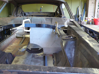
And here is the firewall in place, but waiting for the recesses to be cut & welded in to cater for the offset of the heads on one side of the engine-block (American drivers side) as well as the pedal-box & steering wheel mounting plate on the other side.
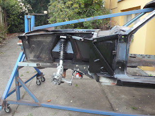
As you can see below, I've plug-welded the new firewall on its edges, but seam-welded it to the new floor panels and up along the full length of its top edge (where it welds to the firewall/shock-tower brace).
The photo below shows the car spun on its side so you can see the seam weld along the firewalls top edge.
It was great to finally receive my under dash brake booster from RRS. This unit includes the clutch pedal assembly too - so all hydraulics except the remote reservoirs are concealed. While this really cleans up the engine bay, I've had to do this anyway so the big-block will fit. The quality of the unit is first-class and it bolted right in with very little problem.
The photo below shows things close to complete. I've grafted the firewall section from the original firewall in place to allow the RRS under dash pedal-box to bolt in. You will also notice the notched cross-brace and recess in progress. And lastly, it was great to bolt the steering wheel & column back in - as that makes it start to look like a real car again. You can see I did a trial fit that included the steering rack to ensure no binding in the universal joints would occur.
In terms of strength, the shell will be quite rigid I'm sure. No doubt I'll "pay" for that however with a harsher ride, but that's a small price in my opinion. Something I will need to keep an eye on now though is the front pillars (where they join the cowl and roof) - as this would be my logical weak spot(s) and thus a place to flex and cause paint cracking. More on what I'm doing to mitigate that potential problem in another post though.....

Friday, 28 August 2009

Firewall & Engine fit.

After dummy fitting the engine for the first time, i've had to modify the sump to clear the rack & pinion and existing front cross-member.

You can see below how I scalloped it and radiused the edges. I've also allowed enough room to shift the block forward or back a few inches from my initial "default" location.

There is still a good half inch or more room between the spinning crank & rods and the bottom of the sump at the new scalloped section.
Now you can see the block being "enticed" into position......

All ancillaries that need to be catered for (for firewall and extractor construction) are bolted on so I don't get surprises when doing the final installation.
Now you can see the Tremec bolted up and i've raised the tran's tunnel 2 inches to give me just enough "wiggle-room" to make future driveline installations easy enough as well as include the cross-member that welds in between the frame extensions at this point. Thankfully, the standard rear engine mount from an Australian '72 to '79 Falcon bolts right onto the Tremec with no mod's and fits perfectly between the frame extensions. I have however had to modify Mustang floor pans to clear the rear cross-member "humps" (that allow for the twin exhausts to pass thru).

Below you can see the block now sits nicely in the engine bay and the transmission is perfectly centered.

And below you can see (if you enlarge the photo) the room I have available to construct my custom headers....
I had a single sheet of steel for the firewall, but had to split it in the middle to make it easiest to handle and "custom fit". You can see from the photo below that it's initially a nice snug fit around the driveline. But this is an illusion - I will be cutting and bending the firewall to make more clearance room. Otherwise the fit would be so tight that I couldn't install the engine/transmission in a single unit, and, i'd struggle to swap to an auto in the future.

Notice the marker pen scribble on the sheet-metal.... this is where I am "indenting" the firewall to provide adequate clearance around the motor.

And below you can see the tight fit with the final positioning. But the important thing is that it does fit!

And finally below you can see my "helpers" having a bit of fun!

When I get back from my travels it's out with all the driveline & suspension, then the shell goes back up on the spinner so I can cleanly weld in the firwall & floor to finish the shell.

Wednesday, 29 July 2009

Firewall - interim update

Just so I can keep from being accused of neglecting this blog, here are some shots of what's been happening recently.......

As can be seen, I've dropped the shell off the rotisserie as I need to dummy fit the engine and can't do that while it's up on the spinner.

But in order to test fit the driveline (to complete the firewall), I had to finally receive my......
  • Tremec TKO 600
  • Quicktime bell housing
  • Flywheel (lightened)
  • Clutch (11 inch, plus hydraulic throw-out bearing)
  • Reduction starter
  • Rocker covers
  • plus various miscellaneous parts


As can be seen above, these allow me to "button up" the block enough to keep it sealed from dirt & humidity yet have the outside dimensions in place to form the firewall and trans-tunnel.

Pictures of first attempted "engine fit" are shown below. There is just under an inch of clearance from the top of the shock towers to the rocker covers.

I can drop the engine down anther inch or two and still have the bell housing sit high enough from the ground - after I cut out some of the dry-sump where it contacts the rack & pinion setup. As I'm having a front and rear sump scavenge system, scalloping the centre section slightly is no problem.

The tall rocker covers fit over the stud girdle. It's a tight fit in terms of engine bay width - but it fits non-the-less. The shot above shows how far back I can set the block for better weight distribution.

However, I am seriously considering fabricating some "sliding" engine mounts to push it back a further 2 inches (once I drop it an extra inch after the sump mod's). The motor would then slip back in under the lower cowl panel nicely. Sliding mounts would then let me slide the engine forward quickly when I need to lift the rocker covers.

Anyway, lot's to do now in terms of "Metalwork 101" to get the firewall sheetmetal right.

Regards, Spiderman.

Monday, 6 July 2009

Installing the RRS steering rack

I thought this would be worth a small post while I wait for the under-dash pedal box.....
Here is the RRS rack I just received & unpacked. It comes complete with the universal-joints, telescopic steering shaft, bearings and all the goodies to modify the steering column as well.


And here it is an hour or so later after it bolted right in with no dramas at all.


As per the instructions, all I needed to do was drill 4 holes (2 each side) in the lip of the chassis rail and in it all went.

One thing I have noticed is that the rack bolts in right where the chassis lip is recessed (cut back) to give clearance for the inner rear edge of the tyre at full steering lock. We will see if there is any interference later I guess when I put on my chosen rim/tyre combo. At least the steering bump-stops are adjustable on the rack so I can ensure I can stop the tyre hitting if there is a problem. But of course I'd rather get as much steering lock as possible so hopefully this wont be an issue.

The rack & struts are just dummied in place so I can get the shell rolling to do the firewall. I need it rolling so I can put the motor in - and I can't do that on the rotisserie!

Friday, 22 May 2009

Shock-Tower Bracing

As mentioned (in the last temporary post), I've been doing a lot of work bracing up the front of the cowls in preparation for trial-fitting the RRS front suspension pieces.

This is all being done in order to have everything complete so I can finally build my custom firewall. It is turning out that the firewall will be the last thing done to complete the shell - when I initially thought I could have completed it much sooner.

However - I've made some useful progress recently as evidenced by the following photos....


What you'll see above (once you look past the very nice RRS strut) is the reasonable degree of "triangulation" happening that stops the top of the shock-tower deflecting inwards (wanting to at least) when the suspension loads up. This custom system does away with the normal Mustang "Export Brace" that would otherwise take room away from big-block induction system in the engine bay.

The RRS gear is sensational quality and bolted right in. I have no hesitation in recommending their products in terms of "fit" as well as great service. I'm confident the performance will match the early impressions - and in case you are wondering, I'm not being sponsored by anyone! Just my actual observations so far!


I done away with the export brace not just to make more room, but also as the export brace is just a pressed piece of thin steel plate that can flex under compression. My system (when under suspension load) comes under tension along the external brace and compression only along the short inner (25mm X 50mm box-tube) brace.


My theory (just my opinion) is that my short inner brace will not flex under compression and my external brace will not stretch. Hence the need to have that solid box-tube section welded in place right across the firewall (see my previous post). I have gone down this path to ensure I have a solid foundation to handle the big-block torque output in combination with the advanced suspension setup.


Lastly, my vehicle engineer suggested I do not weld all this bracing to the shock-tower in place but bolt it in where possible. This allows for some flex to make sure welds aren't prone to cracking over time. And it can all be removed if required.

Here are some shots of how I got to this point.....

This (above) may look simple, but it wasn't. The outcome is that I've braced the firewall support box-tube that you can "end on" at upper left. The painful part is that I had to perform significant rust repair at the window pillar and along the lower edge of the outer cowl to make things solid, as well as build in a drain for the lower cowl. You can see the drain slot (a drain "tube" actually) cut into the upper brace.

The shot above shows the mounting points for the custom bracing being done as well as the "load spreader" plate bolted on top of the shock-tower. Note to young players - install the rear engine bay aprons after doing such work - you'll have much more room. D'oh! Thankfully I had only done one side by this stage.

Above is a shot of the custom bracing that is completely removable. Things to note are that the mounting bolt holes that run through the bottom of each piece of bracing (when looking at the photo above) are sleeved with 1/2"o.d. tube - so that 3/8" high tensile bolts slide nice and snugly through them. Also, the load spreader plates are made from 6mm steel plate & have their tabs bent to face as directly as possible along their lines of "load". Lastly, the three holes drilled into the load spreaders plates match the template created by the RRS strut mounting plates.
The above photo shows the bracing partially complete and gives you an idea of the degree of "triangulation" I was able to get. Quite a bit as you can see. Not much will get in the way of the big-block now!
I have a few more things to do with the front suspension like run the brake lines and tidy up unused holes in the engine bay, while I wait for the RRS under-dash pedal assembly to arrive. It is only then that I can "dummy up" the motor & transmission as well as the pedal box & steering column to fabricate the firewall correctly.
Just so you know, I've decided not to install a firewall from a modern Falcon as I'd need to chop it to pieces anyway (plus it has a resin sound deadening layer sandwiched within it that would catch fire when welding to make welding a real pain). So I'm making the firewall from 1.5mm zinc coated steel sheet and will shift the big-block back as far as possible in the engine bay. This should make the custom firewall quite a contorted piece - but all the recesses & bends that it will need to have will also make it very strong (as it will attain a kind of "3D" shape). So it wont be just a simple shallow "cone" pressed in a flat steel sheet as is done for a normal firewall.
Of course all that will be detailed in upcoming posts.....

Tuesday, 24 March 2009

Cowl Repair and Front Suspension Brace

Hi again.
This will be an evolving post as I don't really know how long this particular stage will last.

As you can see from the photo below, my cowl had plenty of rust in the usual places once i'd removed all the guard support flanges (and removed layers of silicon filler!).
My approach for this stage is as follows.....
  • Cut away the upper cowl in a way that it can then be "removable" - as per Australian Falcons of the early 1970's (and no cuts/joins will be visible). A trap with Mustangs is that as the upper & lower cowl panels are installed as a welded unit, you can never get adequate access to properly rust-proof them at the welded joins (or at least not without great difficulty!). By making the upper cowl removable (attached with just a few screws), I can apply a very effective rust treatment and always have access to this area when required (like removing leaves from vents & fan blades).
  • Fix any rusted areas & "rust proof" the cowl as described above.
  • Install a full-length section of box-tube steel across the rear of the engine bay to provide a solid foundation for the lower (and removable upper) cowl, firewall & new front suspension bracing.
  • Install the new rear engine-bay aprons.
  • Install the new cowl "kick panels" (the side panels that run from the door-hinge frame forward to the firewall).
  • Install a new firewall - although this will be only partially completed as I need to test fit the engine (sitting as far back as practical) in order to fabricate the final piece.
Anyway, below is a photo of the original metal after the upper cowl was removed.

Notice the rust holes in and around the vents. This car must have leaked like a sieve when it ran in the wet!
And below you can see the metal I had to remove to get back to a reasonable foundation.
You can also partially see (at the bottom of the photo) the custom box-tube section I had to fabricate that will fit the contour of the lower cowl. It's sitting there after countless trial-and-error "test-fits".
And below you can see that new "cross member" a little better but with the cowl repair well underway. I'm using 1.5mm zinc coated steel sheet for these patches.
And now you can see the cowl vent "stacks" have been fabricated and the new cross-member is also in place. I've also started to trial-fit the rear aprons as they finally have some metal to attach to at their rear ends.
And for those that are interested, that custom cross-member was a very tricky piece to make and to "get right". It needed to curve in 3 dimensions, be symmetrical and fit the cowl such that there were no gaps too wide to be welded.
This video may provide some idea of what is involved in the part of the repair (plus show just how nice a rotisserie is for making this project a little easier!).
One thing i've realised now that i've got this far...... I think i've finally reached a point where I no longer need to repair major rust problems. It's all "finishing off" work from here - hooray!
I'll modify & add to this post as I proceed.....

Friday, 13 March 2009

Front Frame & Rotisserie Support

Readers of earlier posts will know that I had some serious rust damage in the front frame directly beneath where the battery used to sit. I had been avoiding this fix as it was always going to be awkward unpicking the various spot welds that the standard Mustang has in this area (with so many suspension brackets), not to mention the custom metal-work needed for fit a new repair piece.

However, I eventually received my repair panels, so I cut out the old rusted section until I had a solid foundation and then trimmed the repair pieces back to match the "gap". As can be seen here - it's all fixed now! The lower edge of the fender apron is yet to welded back on when this photo was taken.

The shot above is a much better sight than the equivalent photo in an earlier post (taken when I was dismantling the car).

The photo's above and below show how the repair pieces are a superb fit (once you trim them back to match your requirement).

One nice surprise was that the rust caused by the battery leaks over the years only affected the area under the battery. I found "full thickness metal" in the old frame from just beyond the sway-bar mount. I made sure the patch grafted to the old frame at a diagonal angle for a strong bond. Needless to say, the old and new frame were "rust converted" and "rust protected" inside and out.
I needed to repair the front frame (specifically the mounting points for the front bumper-bar) so that I could remove the remaining section of the space-frame and re-mount the rotisserie to these bumper mounting points.
The space-frame needed to go so I can complete the fixes needed to be done to the cowl & firewall, plus clear room for new front suspension bracing I will be fabricating. So..... the front of the car went back up on blocks, the front space-frame was cut out, new mounts were created on the rotisserie, and then bolted to where the front bumper normally mounts.
You can see the setup in the shots below.


Note the huge "air gap" above the front rails with the firewall, rear fender aprons & outer cowl/kick-panels removed. I've put in the temporary upper piece of box-tube just so this gap doesn't shift as the body is rotated during work.
And here you can start to see the rust in the area where the cowl, dash & firewall all join along a spot welded seam that runs right across the engine bay. This seam will be cut out and replaced with a curved length of box-tube. Once the seam is cut out I can fix any rust problems as well as using the box-tube as a more solid foundation for the firewall & (under) dash panels as well as a platform for stabilising the front shock-towers.

But that will be shown in the next post!